Dry sump oil tank assembly

a technology of oil tank and sump, which is applied in the direction of auxilary lubrication, machines/engines, non-mechanical valves, etc., can solve the problem of lowering the oil lubricating efficiency

Inactive Publication Date: 2006-03-28
GM GLOBAL TECH OPERATIONS LLC
View PDF12 Cites 44 Cited by
  • Summary
  • Abstract
  • Description
  • Claims
  • Application Information

AI Technical Summary

Problems solved by technology

However, the lubricating oil which is pumped from the sump contains a large quantity of air, which has been absorbed into the oil due to sp

Method used


Image

  • Dry sump oil tank assembly
  • Dry sump oil tank assembly
  • Dry sump oil tank assembly

Examples


Embodiment Construction

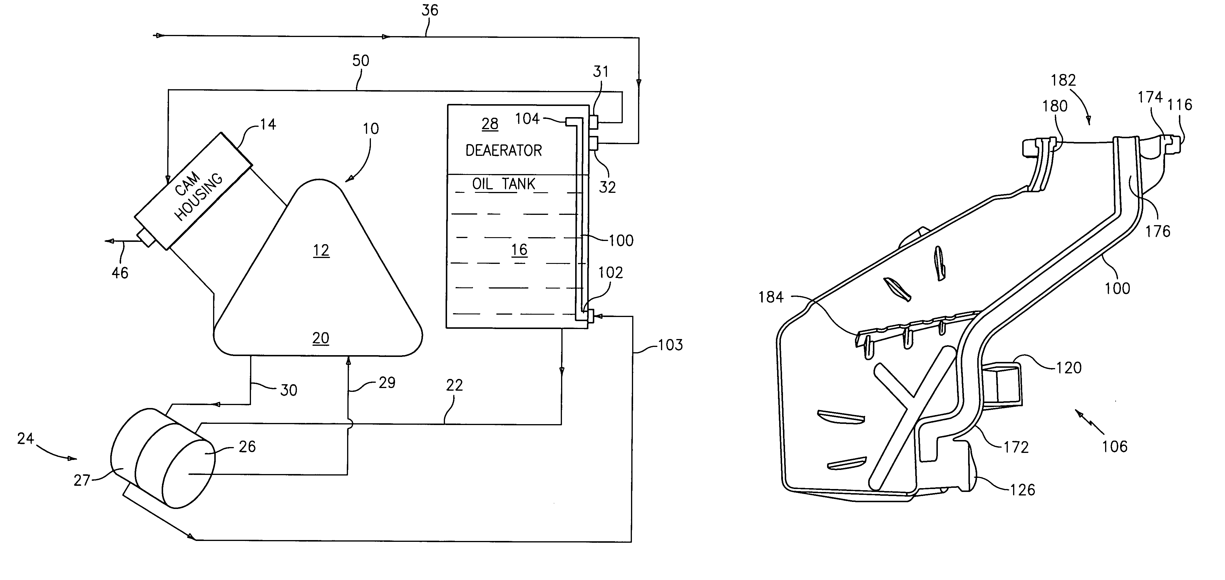
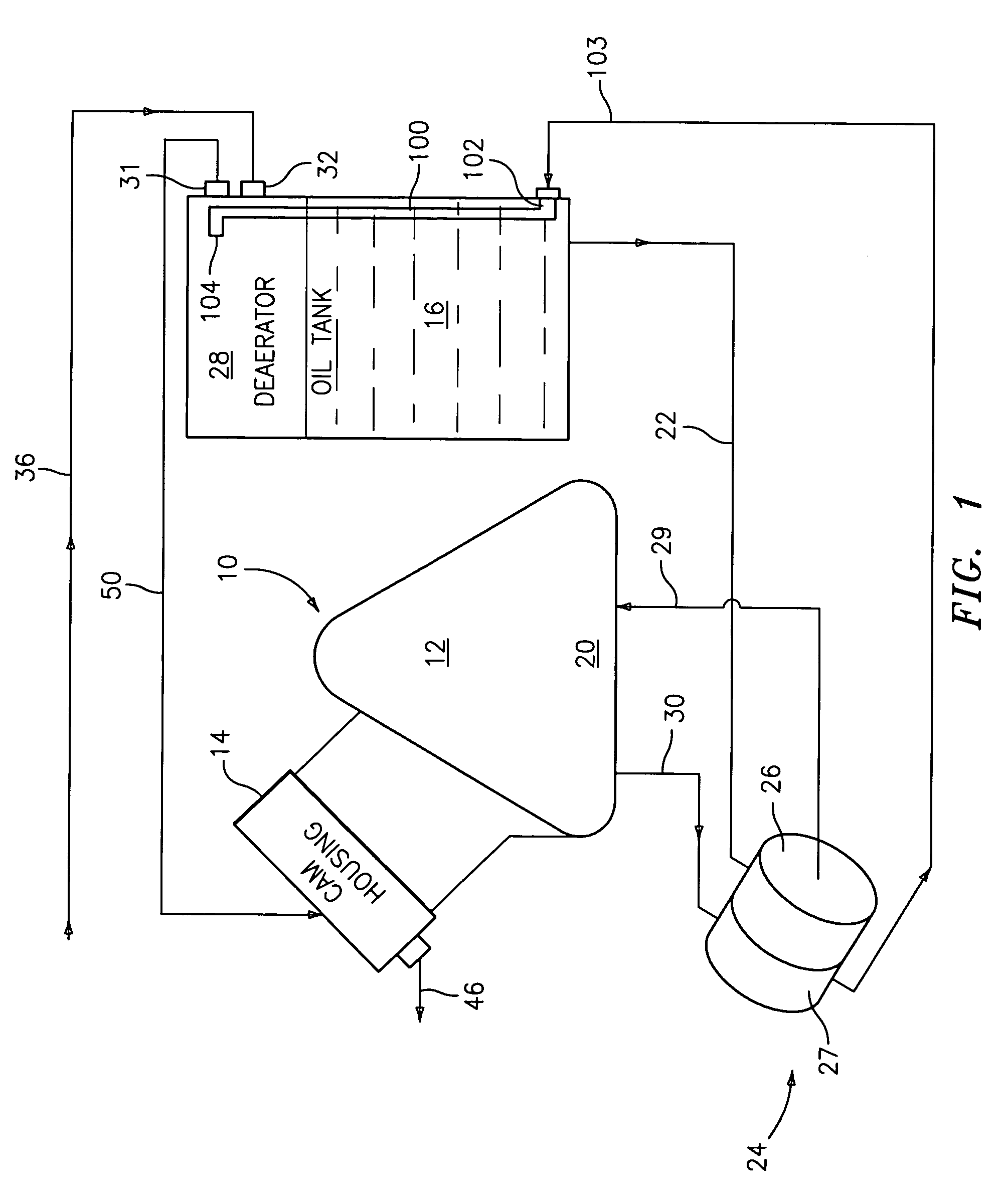
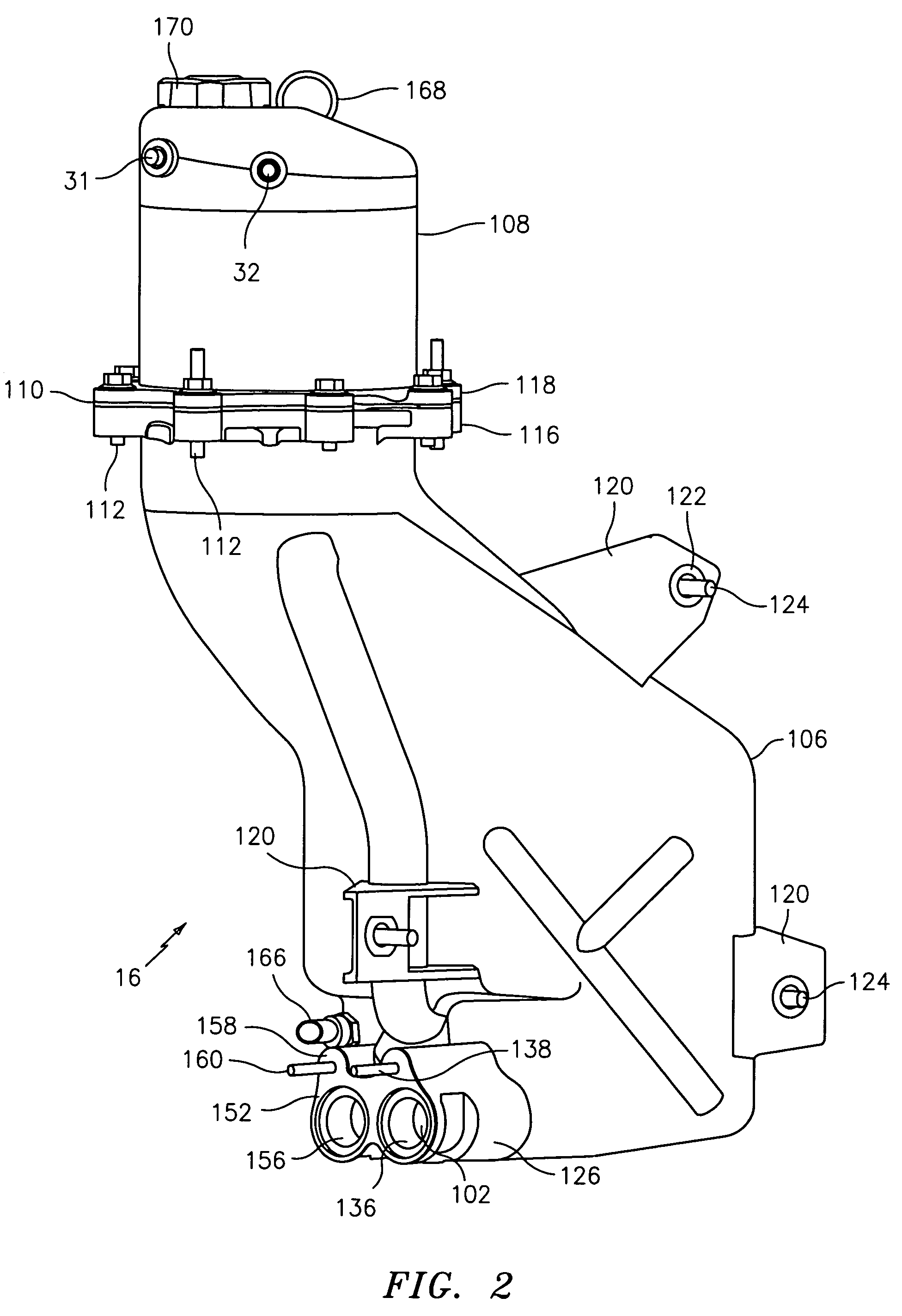
[0019]The present disclosure provides an assembly for a return hose from a scavenge pump to be connected at a fitting located on a bottom portion of an oil tank assembly having an integral return tube configured to return oil to a top portion of the oil tank assembly, thus allowing both return and feed hose connections to be made at the bottom portion of the oil tank assembly. This allows the two hoses necessary to circulate oil to and from the oil tank assembly to be run parallel to each other low in the underhood environment. In one embodiment, this allows the two hoses to be routed underneath an exhaust system and next to a front suspension of a vehicle.

[0020]Referring now to FIG. 1, an engine 10 having a crankcase 12 includes a sump 20 in a lower portion thereof. Engine 10 includes, but is not limited to, an internal combustion engine, such as a motorcycle engine, high performance engine, racing engine or an aircraft engine which operates at relatively high revolutions per minut...


PUM


Abstract

A tank assembly for a dry sump lubrication system for an internal combustion engine is disclosed. The tank assembly includes a tank having an upper tank portion and a lower tank portion. An interface assembly is disposed at the lower tank portion and is configured to operably deliver and receive a lubricant to and from the engine. A first end of a return tube in fluid communication with a second end is configured to receive lubricant from the engine at the interface assembly. The second end opposite the first end is in fluid communication with the upper tank portion. In this manner, a return hose and a feed hose may be connected to a same portion of the tank assembly.

Description

BACKGROUND[0001]The present disclosure relates generally to a lubrication system for an internal combustion engine and, more particularly, to a dry sump lubrication system including an oil tank located outside of the engine crankcase.[0002]Most production cars have a wet sump lubrication system, where the sump is an area below a crankshaft of the engine. In a “wet” sump, the lubricant such as oil is stored beneath the crankshaft in an oil pan. Typically, the oil pan needs to be large and deep enough to hold about four to six quarts of oil.[0003]In a dry sump lubrication system, extra oil is stored in a tank outside the engine rather than in the oil pan. Because a dry sump does not need a large and deep oil pan to hold the oil under the engine, the main mass of the engine can be placed lower in the vehicle.[0004]Dry sump lubrication systems are commonly used with high performance engines such as engines used in motorcycles, high end performance vehicles, racing vehicles, and aircraft...

Claims


Application Information

Patent Timeline
IPC IPC(8): F01M1/16F01M13/00
CPCF01M1/12F01M13/04F01M2001/126
Inventor PATEL, DIPAK R.HOMMES, DANIEL J.
Owner GM GLOBAL TECH OPERATIONS LLC
Why Eureka
Try Eureka