Thermal relief vent and method of manufacturing the same

a technology of thermal relief vents and manufacturing methods, which is applied in the direction of mechanical equipment, functional valve types, transportation and packaging, etc., can solve the problems of exposing workers to hazards, cost of generating and maintaining molten materials, and safety equipment, so as to eliminate many hazards and expenses.

Inactive Publication Date: 2006-03-28
BOSCH FRAN +2
View PDF17 Cites 14 Cited by
  • Summary
  • Abstract
  • Description
  • Claims
  • Application Information

AI Technical Summary

Benefits of technology

[0006]The manufacturing process of crimping a solid ring of fusible material in place with use of the vent cap itself alleviates many disadvantages of the prior art. Namely, use of a room temperature ring of fusible material eliminates many hazards and expenses associated with the use of molten metal. Additionally, use of a ring of fusible material eliminates the problems associated with casting such as air bubbles and partially filled casting chambers. Moreover, crimping of the fusible ring by use of the vent cap itself eliminates the need for holding the cap in place during casting.

Problems solved by technology

There are several disadvantages with such an in situ casting method.
In particular, molten fusible material, such as molten metal, is required which requires subjecting workers to the hazards of handling high temperature molten metals.
There are costs in generating and maintaining the molten material, as well as the safety equipment that must be purchased to work with such molten material.
The in situ casting method, which involves injecting molten metal into a cavity, could result in air bubbles or an otherwise imperfect fill of the cavity, rendering the cast ineffective.
Moreover, an imperfectly filled cavity may not be readily visible or otherwise detectible, such that a defective thermal relief vent may be sold to end consumers and installed on a vehicle.
The logistics of holding the plate in place before, during and shortly after the molten material is poured adds complexity to the in situ casting process.

Method used


Image

  • Thermal relief vent and method of manufacturing the same
  • Thermal relief vent and method of manufacturing the same
  • Thermal relief vent and method of manufacturing the same

Examples


Embodiment Construction

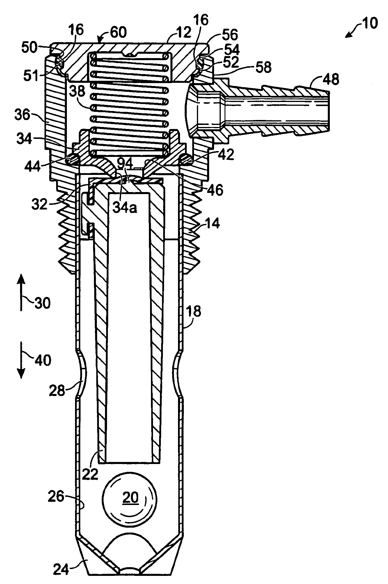
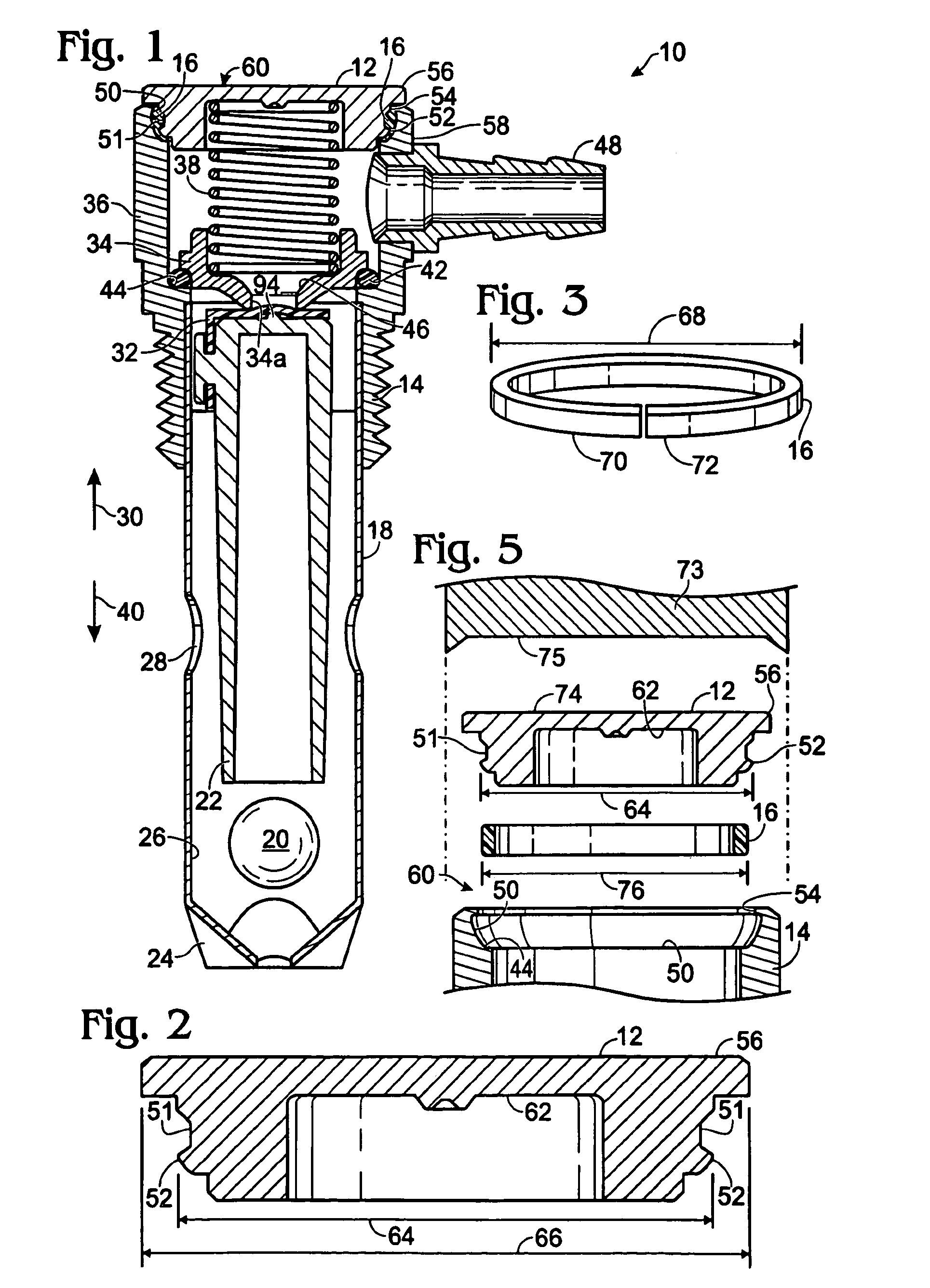
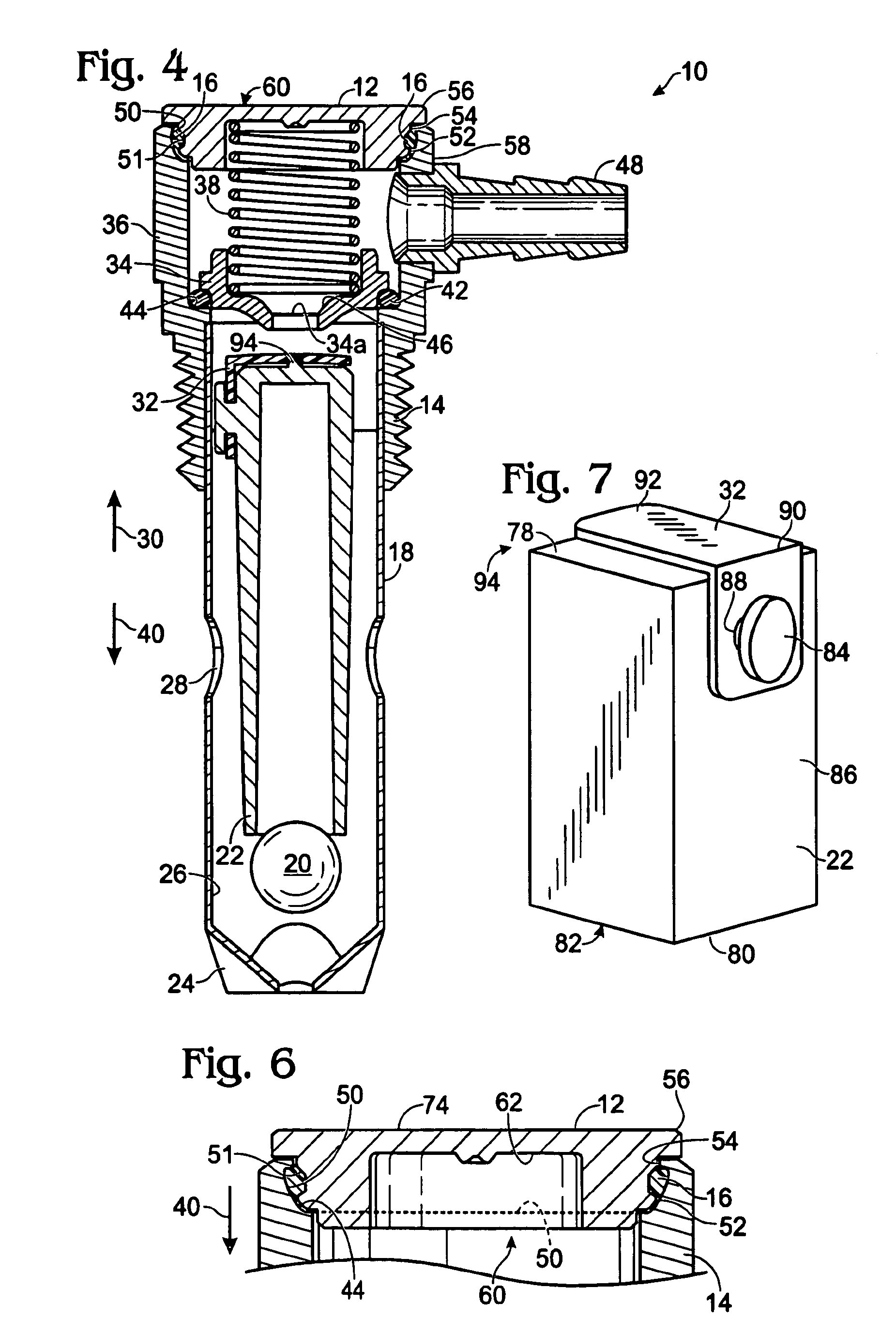
[0019]Referring to the figures, FIG. 1 shows a cross-sectional view of the thermal relief vent 10 with the vent cap 12 positioned on the vent body 14, and a ring of fusible material 16 crimped therein, with the vent shown in a pressurized configuration. In the embodiment shown, vent body 14 comprises an elongate float section 18, also referred to as a cage tube section 18, which houses a ball 20 and a float 22. Cage body 18 includes a crimped end portion 24 which prevents the exit of ball 20 and float 22 from an interior 26 of cage body 18. The crimped end portion 24 and apertures 28 allow fuel and pressure within the fuel tank to communicate with interior 26 of cage body 18. In a pressurized configuration, i.e, when the interior of the fuel tank and therefore the interior 26 of the cage body 18 is subject to a pressure above a first predetermined value, or in the condition of partial tank rollover, the fuel level will cause float 22 to move in a direction 30 within vent body 14 suc...


PUM


Abstract

An improved thermal relief vent for a fuel tank, and a method of manufacturing the same, includes a thermal relief ring that is used to create a mechanical seal within the vent. The thermal relief ring, at room temperature, is crimped in place by use of the vent cap itself. The crimped thermal relief ring creates a mechanical seal between the vent and the vent cap, up until a predetermined thermal relief point, at which time the thermal relief ring will soften and / or yield and release the vent cap from the vent body.

Description

TECHNICAL FIELD[0001]The present invention relates to an improved thermal relief vent for a fuel tank wherein a thermal relief ring creates a mechanical seal within the vent and, more particularly, to an improved thermal relief vent wherein a thermal relief ring is crimped in place by the vent cap. The crimped thermal relief ring creates a mechanical seal between the vent and the vent cap, up until a predetermined thermal relief point, at which time the thermal relief ring will soften and / or melt and release the vent cap from the remainder of the vent.BACKGROUND OF THE INVENTION[0002]Fuel tanks, such as those used on commerical vehicles, are subject to a number of safety requirements. One of these safety requirements is the inclusion of a thermal relief system that allows venting of pressure within the fuel tank when the tank reaches a predetermined temperature. One type of thermal relief system is disclosed in U.S. Pat. No. 5,111,837 to Morris, which discloses a termal relief valve...

Claims


Application Information

Patent Timeline
Patent Type & Authority Patents(United States)
IPC IPC(8): F16K17/38F16K17/14F16K17/40
CPCF16K17/403F16K17/14Y10T137/1804Y10T137/1987Y10T137/1797Y10T137/0491Y10T137/0777Y10T137/3099
Inventor KEEFER, NEAL L.WATSON, KENNETH A.LOFFINK, JOHN A.
Owner BOSCH FRAN
Why Eureka
Try Eureka