
Smooth sleeves for drag and VIV reduction of cylindrical structures

a cylindrical structure and smooth sleeves technology, applied in the direction of sealing/packing, vessel construction, borehole/well accessories, etc., can solve the problems of increasing mooring or station keeping costs, and affecting the lubrication effect of the cylindrical structur

Inactive Publication Date: 2006-03-28
SHELL OIL CO
View PDF30 Cites 39 Cited by
  • Summary
  • Abstract
  • Description
  • Claims
  • Application Information

AI Technical Summary

Benefits of technology

The present invention is a way to control the vibration of a cylindrical object caused by drag and vortex effects. This is done by creating a smooth surface on the object. The invention also includes a system for controlling this vibration in a marine element.

Problems solved by technology

Production of oil and gas from offshore fields has created many unique engineering challenges.
One set of such challenges involves the use of cylindrical marine elements that are susceptible to large drag and vibrations when in the presence of significant ocean currents.
These currents cause drag on the element and cause vortexes to shed from the sides, inducing drag forces and vibrations that can lead to the failure of the marine elements.
Large drag forces can result in increased mooring or station keeping costs as well as the imposition of constraints on what kinds of systems are workable in a current environment (due to stress limitations, top angle limitation while drilling, etc.).
Large vibrations (primarily vortex-induced vibrations) cause dynamic motions that, in turn, cause premature fatigue failures of structural members.
In addition, large vibrations typically cause substantial increases in mean and dynamic drag forces.
Finally, the presence of ocean currents can cause interference between adjacent structures.
However, helical strakes are not very effective at reducing drag, and those are rarely used if drag reduction is important (e.g. drilling risers).
However, there are many instances where the use of fairings is either impractical or uneconomical.
An example is the reduction of drag and VIV for a drilling riser, where fairings can be very difficult to handle and therefore impose large usage costs in terms of lost time due to installation.
Fairings also must typically be quite large and expensive to minimize drag coefficients.
One of these challenges is dealing with effects of currents on fixed cylindrical marine elements.

Method used


Image

  • Smooth sleeves for drag and VIV reduction of cylindrical structures
  • Smooth sleeves for drag and VIV reduction of cylindrical structures
  • Smooth sleeves for drag and VIV reduction of cylindrical structures

Examples


Embodiment Construction

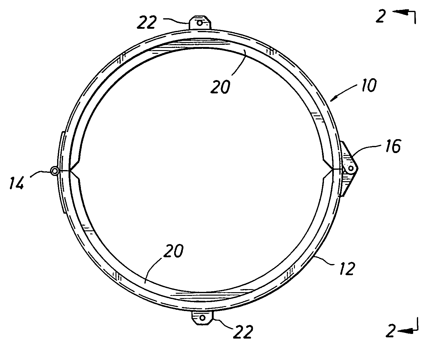
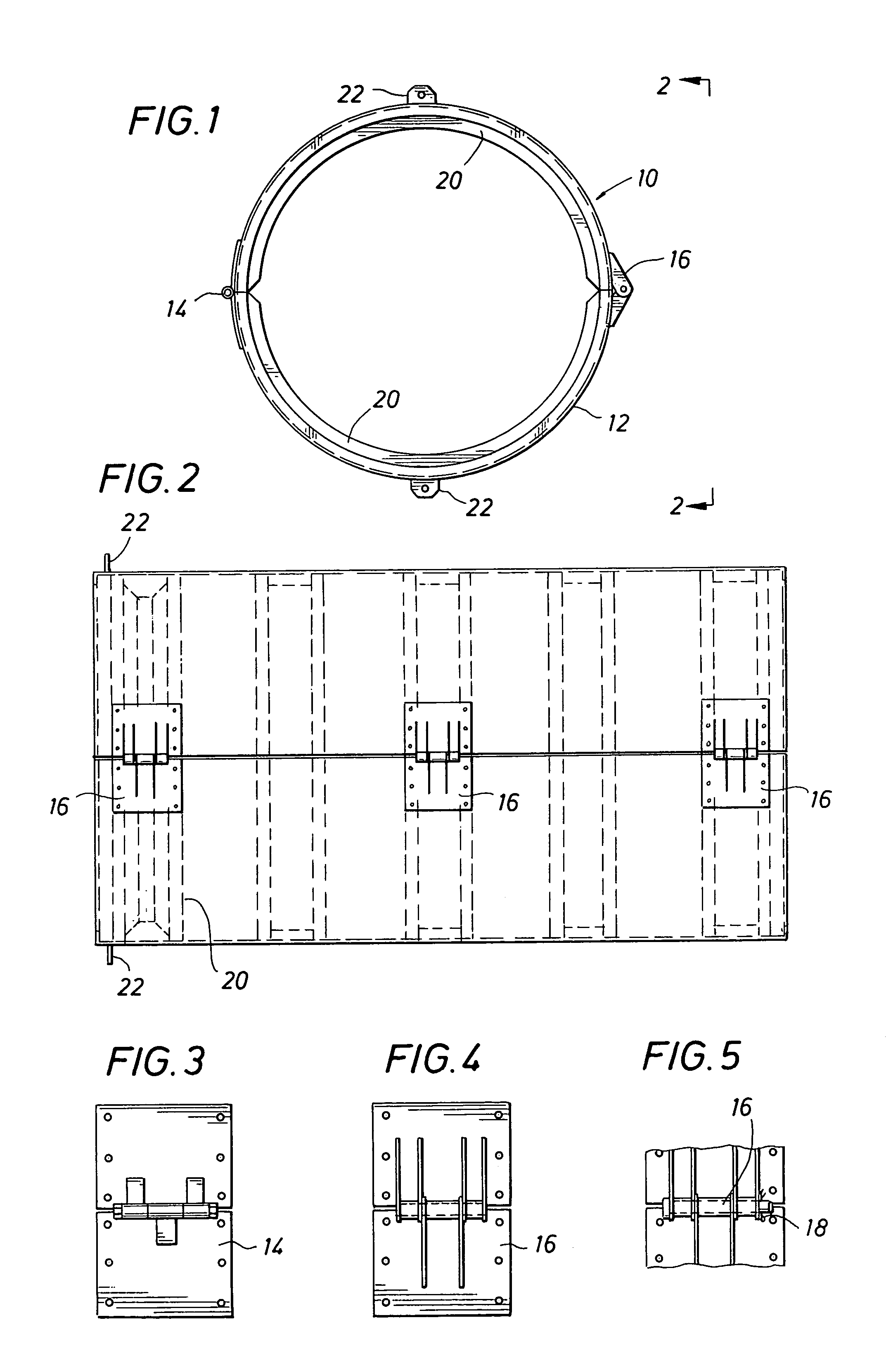
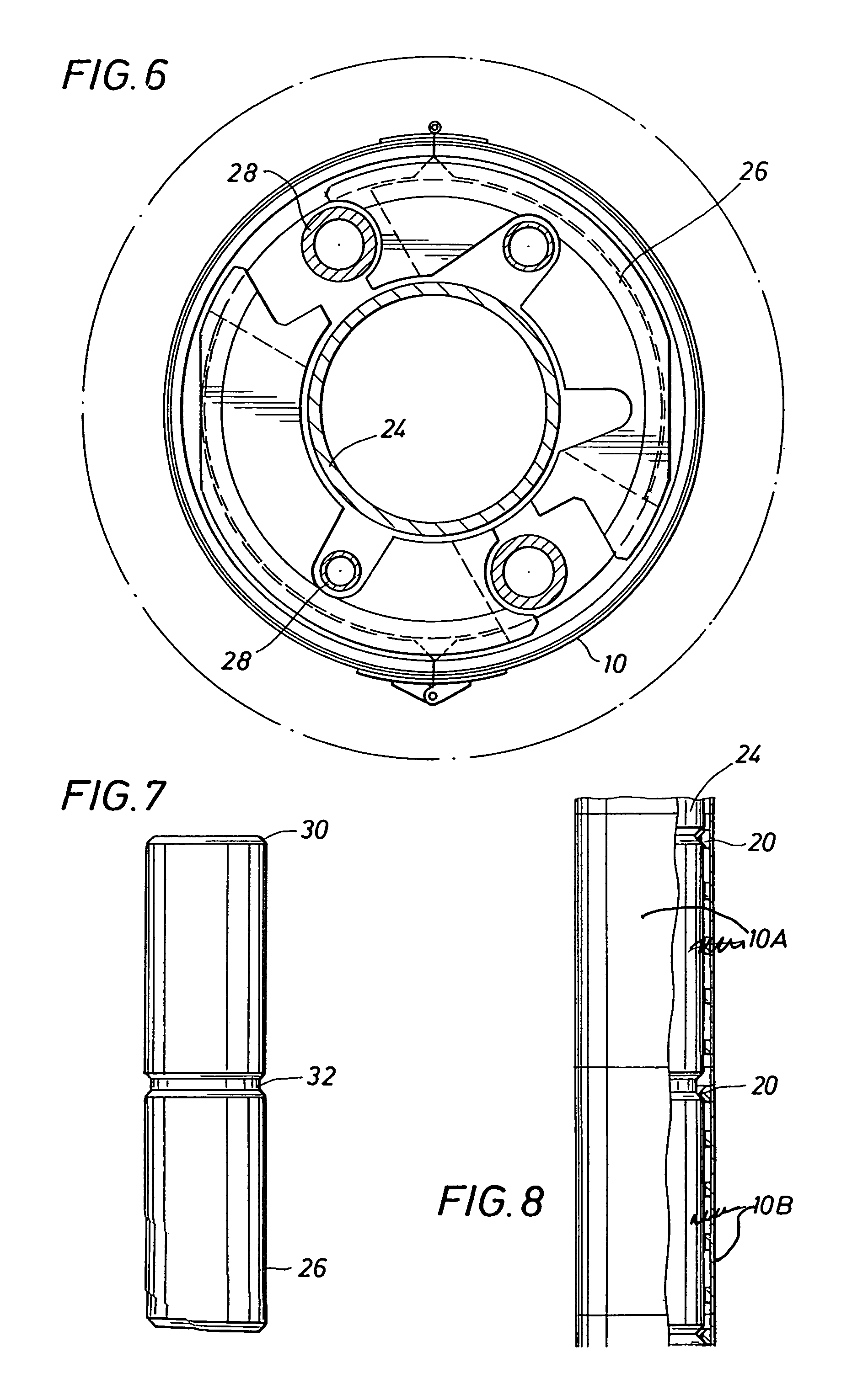
[0023]FIGS. 1 and 2 illustrate a substantially cylindrical sleeve 10 presenting an ultra-smooth surface 12. Here the sleeve is a clam-shell design formed of fiberglass with a gel-coat presenting ultra-smooth surface 12. Opposing sides of the clam-shell are secured with hinges 14 and connectors such as latches 16 which may be secured with a hairpin 18 in one embodiment of the present invention. See also FIGS. 3–4. In FIG. 5, a hinge 16 is shown as secured by pin 18 and retaining ring 19. Lifting provisions may be conveniently provided with lifting eyes 22. Ribs 20 provide some strength to the sleeve 10 and may be formed to axially secure the sleeve about riser sections.

[0024]FIG. 6 illustrates sleeve 10 secured about axially cross sectioned drilling riser 24. A dotted outline also illustrates the diameter of the rotary on the offshore platform. Even though the sleeve is configured to encircle a drilling riser 24, its buoyancy modules 26, and attendant control lines 28, it remains suf...


PUM


Abstract

A method for controlling drag and vortex induced vibration in a substantially cylindrical element by providing an ultra-smooth surface about the cylindrical element. The system for controlling drag and vortex induced vibration utilizes a substantially cylindrical marine element having an ultra-smooth effective surface.

Description

[0001]This application claims the benefit of U.S. Provisional Application No. 60 / 154,289 filed Sep. 16, 1999, the entire disclosure of which is hereby incorporated by reference.BACKGROUND[0002]The present invention relates to a method and apparatus for reducing drag and vortex-induced-vibrations (‘VIV’) and, more particularly, reducing VIV and drag to cylindrical elements in marine environments.[0003]Production of oil and gas from offshore fields has created many unique engineering challenges. One set of such challenges involves the use of cylindrical marine elements that are susceptible to large drag and vibrations when in the presence of significant ocean currents. Such marine elements are used in a variety of applications, including, e.g., subsea pipelines; drilling, production, import and export risers; tendons for tension leg platforms; legs for traditional fixed and for compliant platforms; space-frame members for platforms; cables; umbilicals; and other mooring elements for d...

Claims


Application Information

Patent Timeline
Patent Type & Authority Patents(United States)
IPC IPC(8): E21B17/01E02D5/56E21B31/00B63B21/50
CPCE21B17/012B63B21/502
Inventor ALLEN, DONALD WAYNEHENNING, DEAN LEROYMCMILLAN, DAVID WAYNEMCDANIEL, RICHARD BRUCEDUPAL, KENNETH
Owner SHELL OIL CO
Learn More