Rotary atomizer for particulate paints

Inactive Publication Date: 2006-03-28
DURR SYST INC
View PDF5 Cites 44 Cited by
  • Summary
  • Abstract
  • Description
  • Claims
  • Application Information

AI Technical Summary

Benefits of technology

[0006]The present invention provides a rotary atomizer which provides improved color matching. Generally, the improved atomizer provides a more uniformed pain

Problems solved by technology

Current rotary atomizers are unable to obtain good color matching applying paints with particulates, such as mica.
This second coat provides the proper color; however, air atomized spray guns have a low transfer efficiency (approximately 50

Method used


Image

  • Rotary atomizer for particulate paints
  • Rotary atomizer for particulate paints
  • Rotary atomizer for particulate paints

Examples


Embodiment Construction

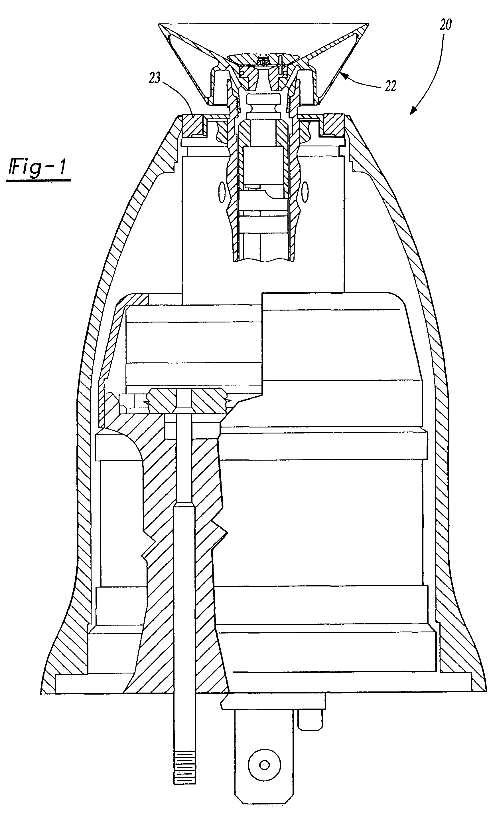
[0018]FIG. 1 illustrates a rotary atomizer 20 and a bell cup 22 according to the present invention. The atomizer includes a shaping air ring 23 which preferably includes 30 nozzles generally parallel to the axis of the atomizer. The shaping air ring 23 supplies shaping air, preferably at 100 liters per minute. With the reduced number of holes from the known shaping air ring (typically 40), this produces increased turbulence by the shaping air.

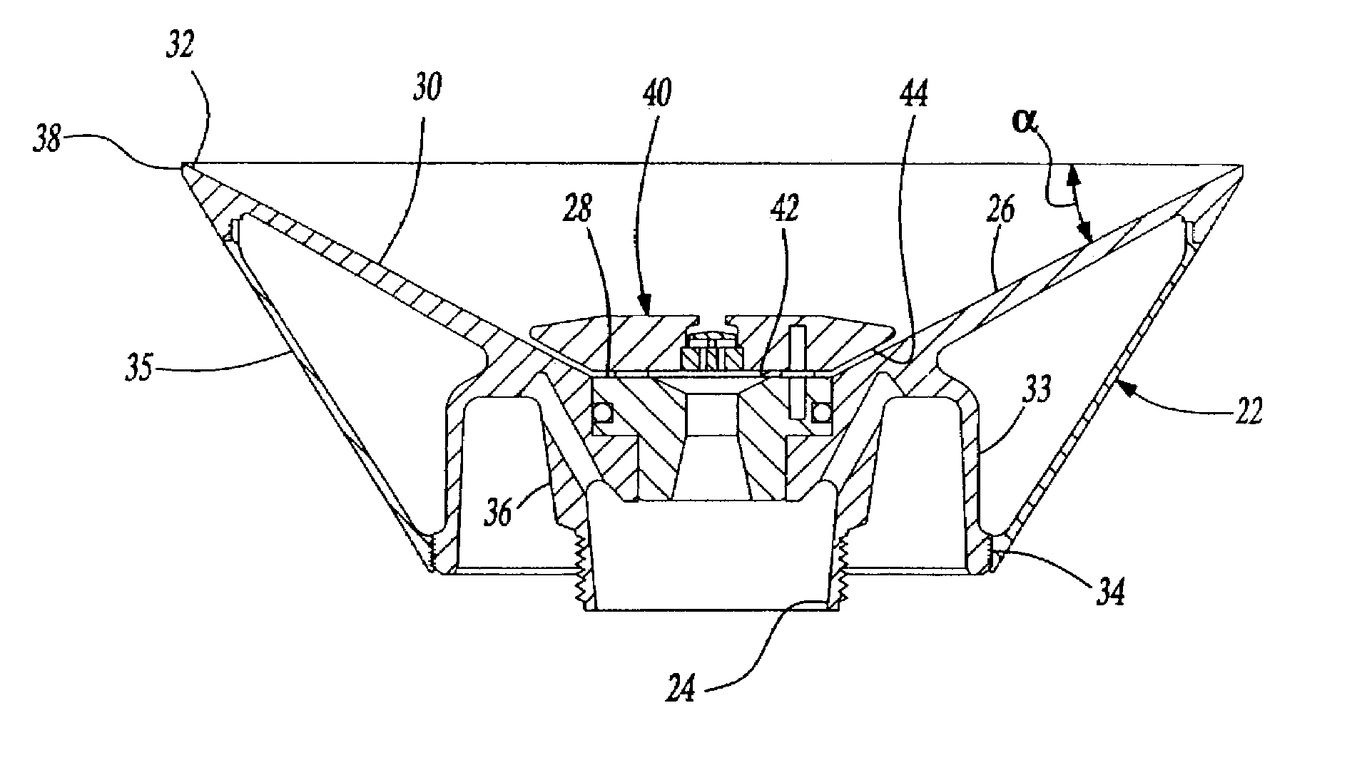
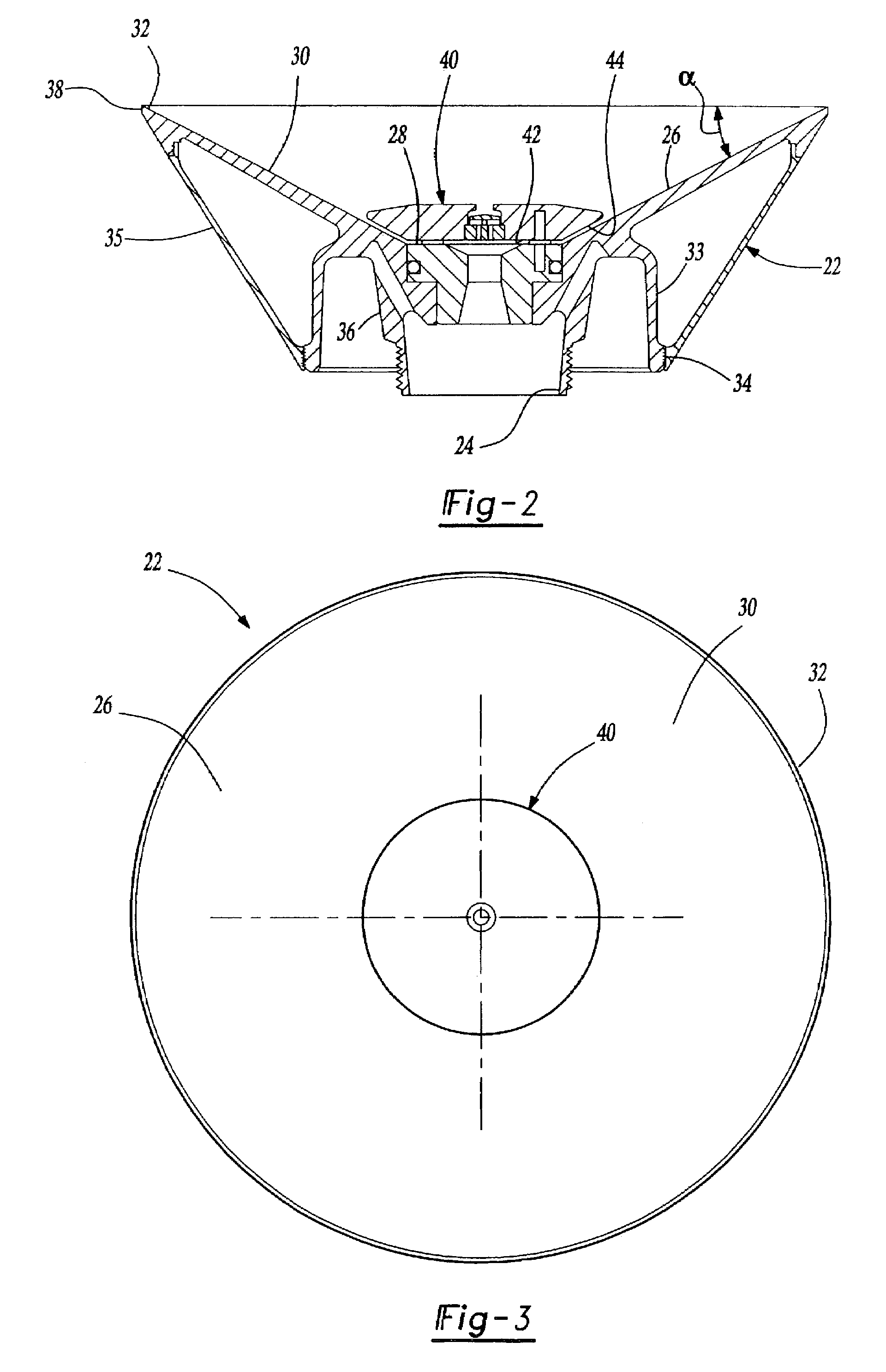
[0019]The bell cup 22 is shown in more detail in FIGS. 2–3. Bell cup 22 includes a central axial opening 24 at the base of the bell cup 22. The central axial opening 24 includes a coaxial passageway onto a front surface 26 of the bell cup 24. The front surface 26 of the hell cup 22 includes a central flat portion 28 generally perpendicular to the axis of the bell cup 22 and a generally conical overflow surface 30 from the perpendicular portion 28 to a spray edge 32. Between the perpendicular surface 28 and the spray edge 32, the overflow surfac...


PUM


Abstract

A rotary atomizer applies particulate paints with good color matching by reducing paint droplet size deviation and then optimizing the other paint spraying parameters. Paint droplet size parameters are reduced by using a bell cup having reduced flow deviations, including an overflow surface having a generally constant angle between a deflector and an atomizing edge.

Description

[0001]This application is a divisional of U.S. patent application Ser. No. 09 / 769,707 filed on Jan. 25, 2001, now U.S. Pat. No. 6,623,561, which is a divisional of U.S. patent application Ser. No. 09 / 271,477 filed on Mar. 17, 1999, now U.S. Pat. No. 6,189,804, and claims priority to U.S. Provisional Patent Application Ser. No. 60 / 079,565, filed Mar. 27, 1998.BACKGROUND OF THE INVENTION[0002]The present invention relates generally to rotary atomizers and more particularly to a rotary atomizer having improved performance for particulate paints.[0003]Currently, many paints are applied by rotary atomizers to work pieces, such as automobile bodies. Rotary atomizers include a rotating bell cup having a generally conical overflow surface between a radially inward central axial opening and a radially outward atomizing edge. At or near the atomizing edge, the angle of the overflow surface relative to the axis of the bell cup decreases sharply to form a lip adjacent the atomizing edge. The pu...

Claims


Application Information

Patent Timeline
IPC IPC(8): B05B1/34B05B3/10B05B5/04B05B7/08B05B13/04
CPCB05B3/1014B05B3/1042B05B13/0452B05B5/0407B05B3/1064B05B7/0815B05B3/1092B05B5/0426
Inventor VETTER, KURTSCHNEIDER, ROLFFISCHER, ANDREASHELDT, ROBERT F.
Owner DURR SYST INC
Why Eureka
Try Eureka