
Light guide panel with slanted light guiding parts

a light guide panel and light guide technology, applied in the direction of lighting and heating apparatus, instruments, mechanical equipment, etc., can solve the problems of reducing performance, increasing manufacturing costs, and remarkably deteriorating brightness, so as to facilitate handling and installation, maximize brightness, and reduce volume and weight of light guide panels

Inactive Publication Date: 2006-03-28
FAWOO TECH CO LTD
View PDF3 Cites 17 Cited by
  • Summary
  • Abstract
  • Description
  • Claims
  • Application Information

AI Technical Summary

Benefits of technology

[0020]Another object of the present invention is to provide a light guide panel with slanted light guiding part(s), wherein the light emitted from the light source can be totally internal-reflected in the light guide panel, so that the brightness can be maximized and the volume and weight of the light guide panel can be reduced to facilitate its handling and installation.
[0021]A further object of the present invention is to provide a light guide panel with slanted light guiding part(s), which can be manufactured in much lower costs than the conventional ones.

Problems solved by technology

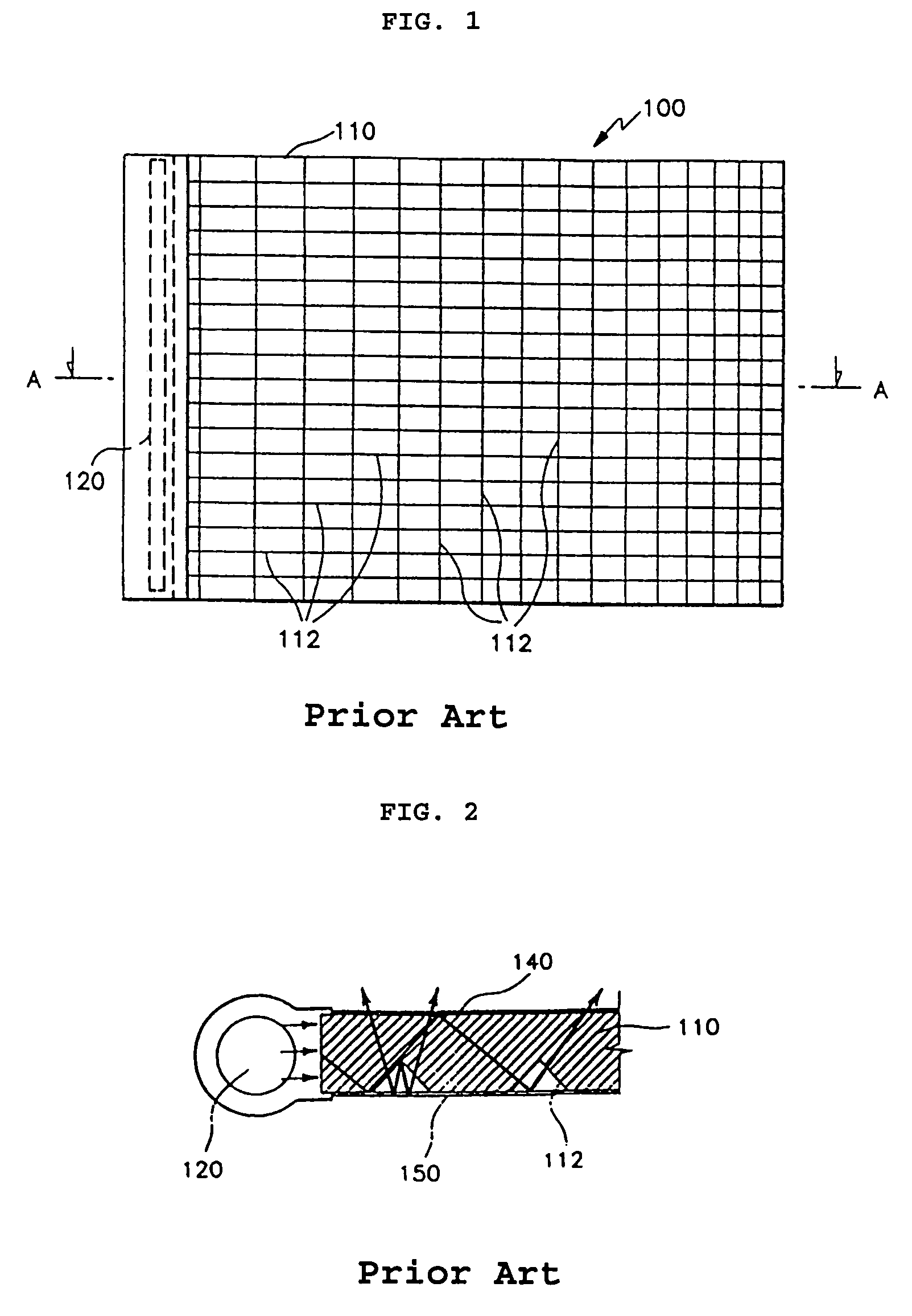
As the width and thickness of the light guide panel must be increased in proportion to the size of the light source, the increased volume and weight of the light guide panel complicate handling and installation, increase manufacturing costs, while the diminishing performance.
However, the brightness remarkably deteriorated much more than the case in FIG. 2 where the light guide panel is as thick as the diameter of the light source.
In order to obtain the uniform brightness, however, the panel has to be manufactured by an injection molding, by which the size and use of the panel is to be limited.
Therefore, the panel can be used only for light guide panels of notebook computers, and cannot be used for middle or large-sized light guide panels.
Firstly, the panel must be molded while passing through between two inclined rollers, but it is difficult to supply raw materials of the panel in proportion to its varying thickness.
Secondly, as the light source differs in pattern and slope according to the lightness, the light source is limited.
Thirdly, many rollers are required since the slopes differ depending on the width of the panel.
Fourthly, in order to install the panel on the wall or the plane, it is necessary to fill the difference between the neighboring stairs with supplement.

Method used


Image

  • Light guide panel with slanted light guiding parts
  • Light guide panel with slanted light guiding parts
  • Light guide panel with slanted light guiding parts

Examples


Embodiment Construction

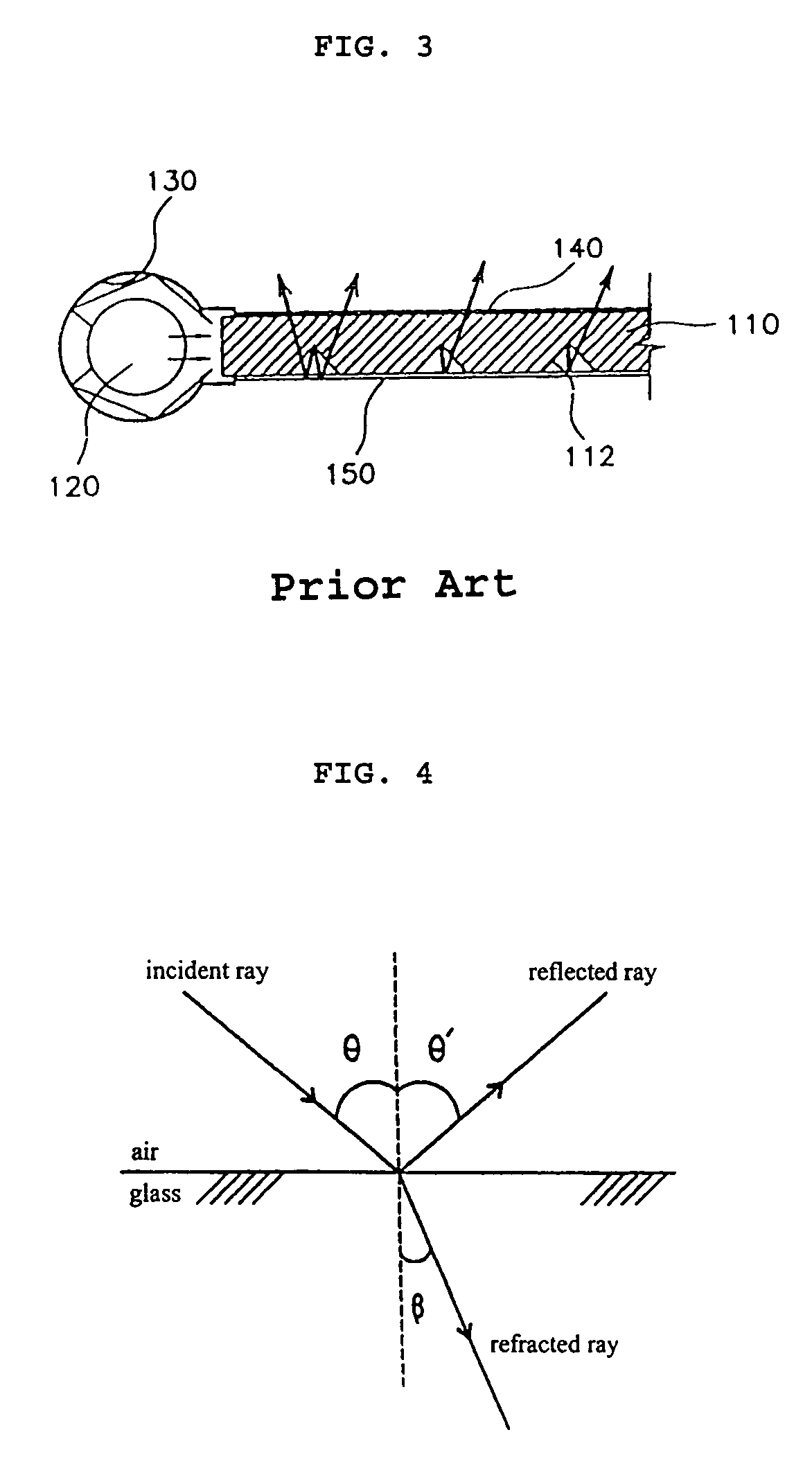
[0035]Due to the nature of light propagating in the shortest route, light is reflected and refracted on the boundary between two different media as shown in FIG. 4.

[0036]For example, when the light falls on a plane glass surface in the air forming the angle (θ) with the normal to the glass surface, it is reflected by the angle (θ′) which is the same as the angle of incidence (θ=θ′), and it is refracted according to the following relation:

n1×sin θ=n2 ×sin β,

[0037]wherein n1 and n2 represent the index of refraction of each medium, and angle β represents an angle of refraction.

[0038]Table 1 shows indexes of refraction of various media (for yellow light ray).

[0039]

TABLE 1mediumIndex of refractionvacuum1air1.00029water (20° C.)1.33acetone1.36glass1.52diamond2.42polystyrene1.55acryl1.49

[0040]Refraction of light takes place when the light falls on the boundary surface between two different media having different optical density, since the speed of progress of light is different in each med...


PUM

PropertyMeasurementUnit
angleaaaaaaaaaa
optical densityaaaaaaaaaa
critical angleaaaaaaaaaa

Abstract

The present invention provides a light guide panel with one or more slanted light guiding parts for backlight units for liquid crystal display (LCD) and for advertisement or illumination, wherein the slanted light guiding part is provided at one side end of the light guide panel, with its one end adjacent to a light source being thicker than the other end adjacent to the light guide panel, to have a slope in which the light emitted from the light source can be totally internal-reflected in the light guide panel, so that the brightness can be maximized and the volume and weight of the light guide panel can be reduced to facilitate its handling and installation, thus resulting in significant reduction of manufacturing expenses.

Description

FIELD OF THE INVENTION[0001]The present invention relates to a light guide panel with slanted light guiding part(s) for backlight units for liquid crystal display (LCD) and for advertisement or illumination, and more particularly to a light guide panel having slanted light guiding part(s), wherein the slanted light guiding part is provided at one side end of the light guide panel, with its one end adjacent to a light source being thicker than the other end adjacent to the light guide panel, to have a slope in which the light emitted from the light source can be totally internal-reflected in the light guide panel, so that the brightness can be maximized and the volume and weight of the light guide panel can be reduced to facilitate its handling and installation, thus resulting in reduced manufacturing expenses.BACKGROUND OF THE INVENTION[0002]In general, a backlight unit for LCD and for advertisement or illumination comprises a light guide panel made of a transparent acrylate board. ...

Claims


Application Information

Patent Timeline
Patent Type & Authority Patents(United States)
IPC IPC(8): F21V7/04G02B6/00F21V8/00F21Y103/00G02F1/13357
CPCG02B6/0046G02B6/0036G02B6/0038G02F1/1335
Inventor YOO, TAE KUN
Owner FAWOO TECH CO LTD
Learn More