Golf ball

a technology of golf ball and ball, which is applied in the field of golf balls, can solve the problems of poor air resistance lowering effect and the degree of compromise of the density of the arrangement of circular dimples, and achieve the effect of enhancing aerodynamic performance and increasing carry

Active Publication Date: 2006-03-28
BRIDGESTONE SPORTS
View PDF7 Cites 20 Cited by
  • Summary
  • Abstract
  • Description
  • Claims
  • Application Information

AI Technical Summary

Benefits of technology

[0008]Therefore, the object of the present invention is to provide a golf ball in which the aerodynamic performance is enhanced by dimple effects, enabling an increased carry to be achieved.
[0009]The inventors have conducted extensive investigations to achieve the above object. As a result, they have discovered that, in a golf ball having a surface on which numerous dimples are arranged with any dimple being surrounded by a plurality of adjoining dimples, the aerodynamic performance is enhanced by disposing between mutually adjoining dimples, each of which is defined by a peripheral edge, a narrowly extending edge element which forms part of the peripheral edge, and by densely arranging the dimples so as to substantially eliminate space for providing lands. The inventors have also discovered that, when the golf ball is manufactured in a two-part mold having two halves, a better flight symmetry can be achieved by arranging the edge elements on or near a ball equator coincident with a parting line between the mold halves so as to be continuously interconnected along the equator and so that some of the edge elements intersect the equator.

Problems solved by technology

Also, because it is critical to arrange dimples as uniformly as possible on the spherical surface of the ball, some degree of compromise on the density of the arrangement of circular dimples has been required.
However, the hexagonal shaped bounded areas delineated by the lattice members lie on a spherical surface having a center that coincides with the center of the ball and are not dimples, thus having a poor air resistance lowering effect.

Method used


Image

  • Golf ball
  • Golf ball
  • Golf ball

Examples


Embodiment Construction

[0025]The golf ball is described in detail below in conjunction with the attached diagrams.

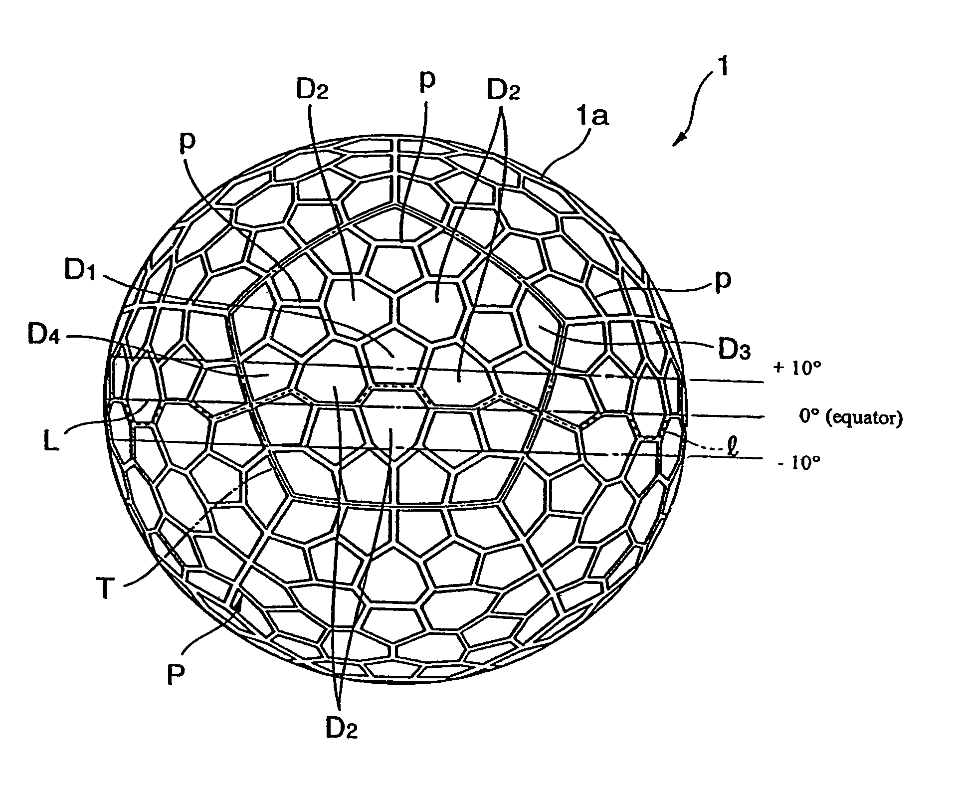
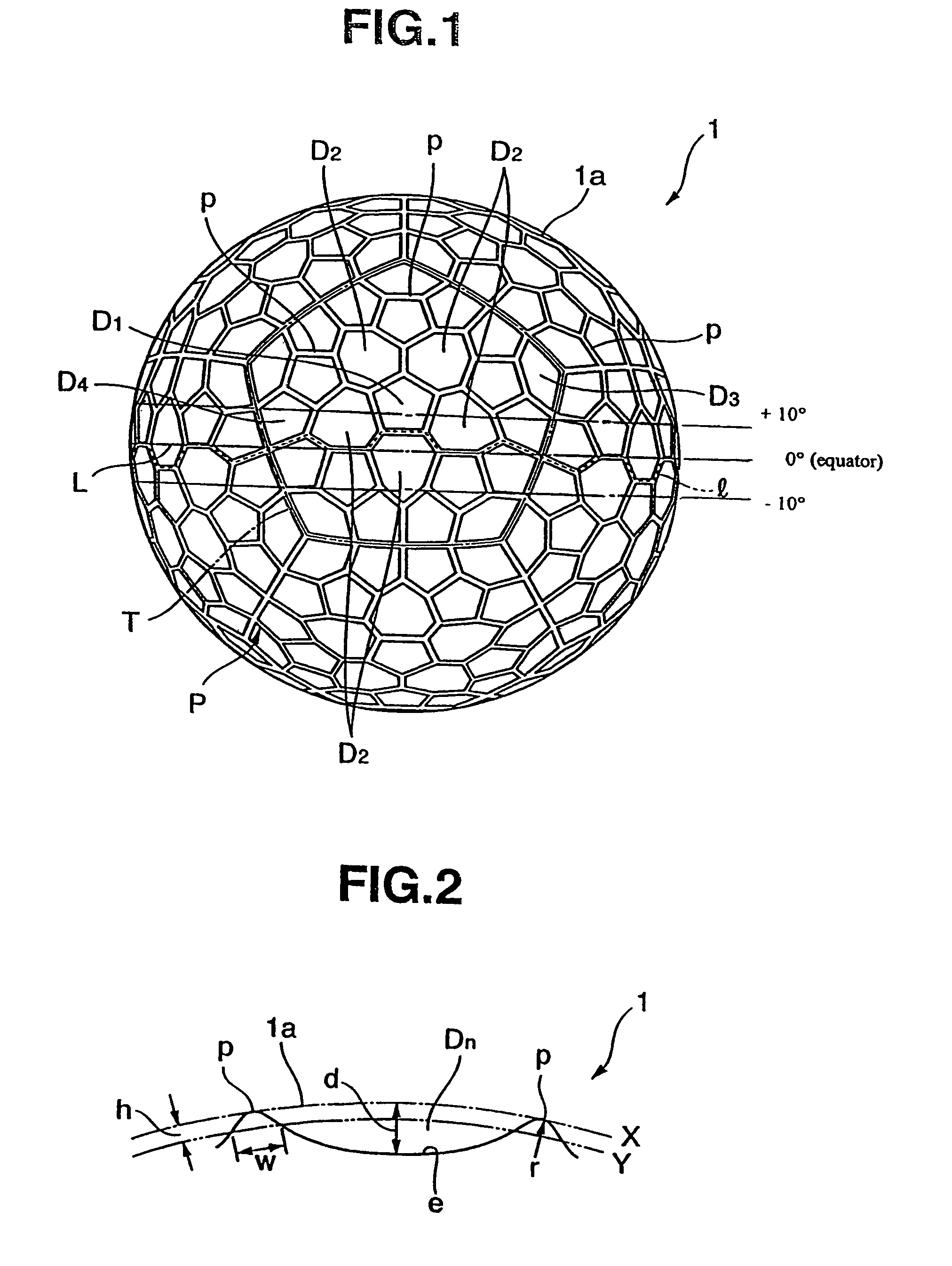
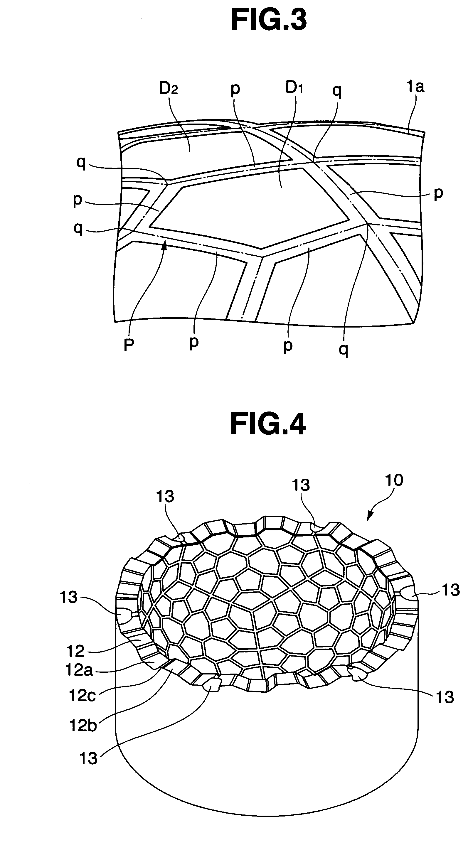
[0026]FIG. 1 is a plan view of a golf ball 1 illustrating a first embodiment of the invention, FIG. 2 is an illustrative view showing part of the ball surface, and FIG. 3 is an enlarged view of a portion of FIG. 1.

[0027]In the golf ball 1 according to one embodiment of the invention, as shown in FIG. 1, numerous dimples are arranged on the ball's surface 1a with any dimples D1 and D2 being surrounded by a plurality of adjoining dimples. Specifically, FIG. 1 shows, as examples of any dimples, one pentagonal dimple D1 positioned at the center of a unit pentagon T on a spherical dodecahedron (which dimple is referred to hereinafter as the “center dimple”) and five heptagonal dimples D2, D2, D2, D2 and D2 disposed around the center dimple D1. The center dimple D1 and the heptagonal dimples D2 that adjoin it have formed therebetween edge elements p which make up part of the peripheral edge P of the...


PUM


Abstract

A golf ball has a surface on which numerous dimples are arranged with any dimple being surrounded by a plurality of adjoining dimples. Mutually adjoining dimples, each defined by a peripheral edge, have disposed therebetween an edge element which forms part of the peripheral edge. When the golf ball is manufactured with a two-part mold having two halves, the edge elements on or near a ball equator coincident with a parting line between the mold halves are continuously interconnected along the equator and some of the edge elements intersect the equator. The golf ball has dimple effects which enhance its aerodynamic performance and thus increase its carry.

Description

BACKGROUND OF THE INVENTION[0001]The present invention relates to a golf ball having an excellent flight performance.[0002]It is well-known that, in a golf ball, the high rebound of the ball itself and the air resistance-reducing effects during flight by dimples arranged on the ball's surface play important roles in enabling the ball to achieve a long carry when hit. A variety of methods have been devised for arranging dimples as densely and uniformly as possible on the surface of the ball so as to reduce air resistance.[0003]The dimples ordinarily employed are depressions that are circular as viewed from above. Because such circular dimples are used, even if, in order to arrange the circular dimples to a high density, neighboring dimples are placed so closely to each other that the width of the land separating two dimples approaches zero, lands of a certain size having triangular or quadrangular shapes of a certain extent are formed in areas surrounded by three or four thusly arran...

Claims


Application Information

Patent Timeline
Patent Type & Authority Patents(United States)
IPC IPC(8): A63B37/12A63B37/00
CPCA63B37/0004A63B37/0009A63B37/002A63B37/0019A63B37/0012
Inventor KASASHIMA, ATSUKISATO, KATSUNORI
Owner BRIDGESTONE SPORTS
Why Eureka
Try Eureka