
Chain tensioner

Inactive Publication Date: 2006-03-28
HONDA MOTOR CO LTD
View PDF8 Cites 10 Cited by
  • Summary
  • Abstract
  • Description
  • Claims
  • Application Information

AI Technical Summary

Benefits of technology

[0008]The invention is made in view of such a problem and an object is to provide a chain tensioner in which the enhancement of an oscillation absorption function for a transmission chain of a tensioner arm and the enhancement of wear resistance can be simultaneously achieved.
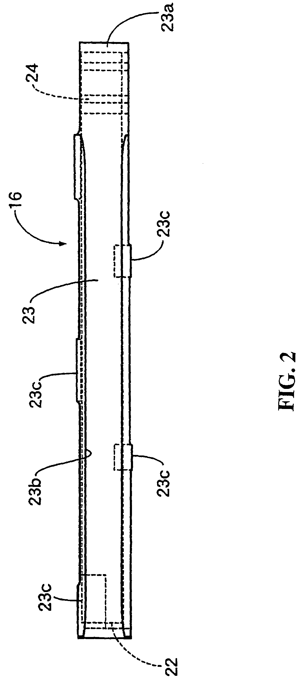
[0011]According to the present invention, as the flexibility of the middle of the tensioner arm body is enhanced, an oscillation absorption function for the transmission chain can be enhanced and the width of the tensioner arm body is different in each part, the natural frequency of the tensioner arm body is different in each part and the resonance of the tensioner arm body can be also prevented.
[0012]In addition, in a location in which the width of the tensioner arm body is small, as the tensioner shoe is provided with the chain guide groove to which the transmission chain is fitted though surface pressure between the tensioner arm body and the tensioner shoe being large, surface pressure between the tensioner shoe and the transmission chain is not particularly large and the durability of the tensioner arm can be secured without damaging the wear resistance of the tensioner shoe.
[0016]According to the present invention, the flexibility of the middle of the tensioner arm body is enhanced, an oscillation absorption function for the transmission chain can be enhanced, the natural frequency is different in a part with the hole and a part without the hole in the tensioner arm body and the resonance of the tensioner arm body can be also prevented.
[0017]In addition, in the periphery of the hole of the tensioner arm body, surface pressure between the tensioner shoe and the transmission chain is not particularly large because the tensioner shoe which is provided with the chain guide groove to which the transmission chain is fitted though surface pressure between the tensioner arm body and the tensioner shoe is large and the durability of the tensioner arm can be secured without damaging the wear resistance of the tensioner shoe.

Problems solved by technology

Thus, a problem occurs wherein the surface pressure between the tensioner arm and the transmission chain increases and the wear resistance of the tensioner arm is deteriorated when it is attempted to narrow the width of the middle of the tensioner arm, to enhance the flexibility of the middle and to enhance the oscillation absorption function for the transmission chain.

Method used


Image

  • Chain tensioner
  • Chain tensioner
  • Chain tensioner

Examples


Embodiment Construction

[0033]Suitable embodiments of the present invention shown in the drawings will be described below.

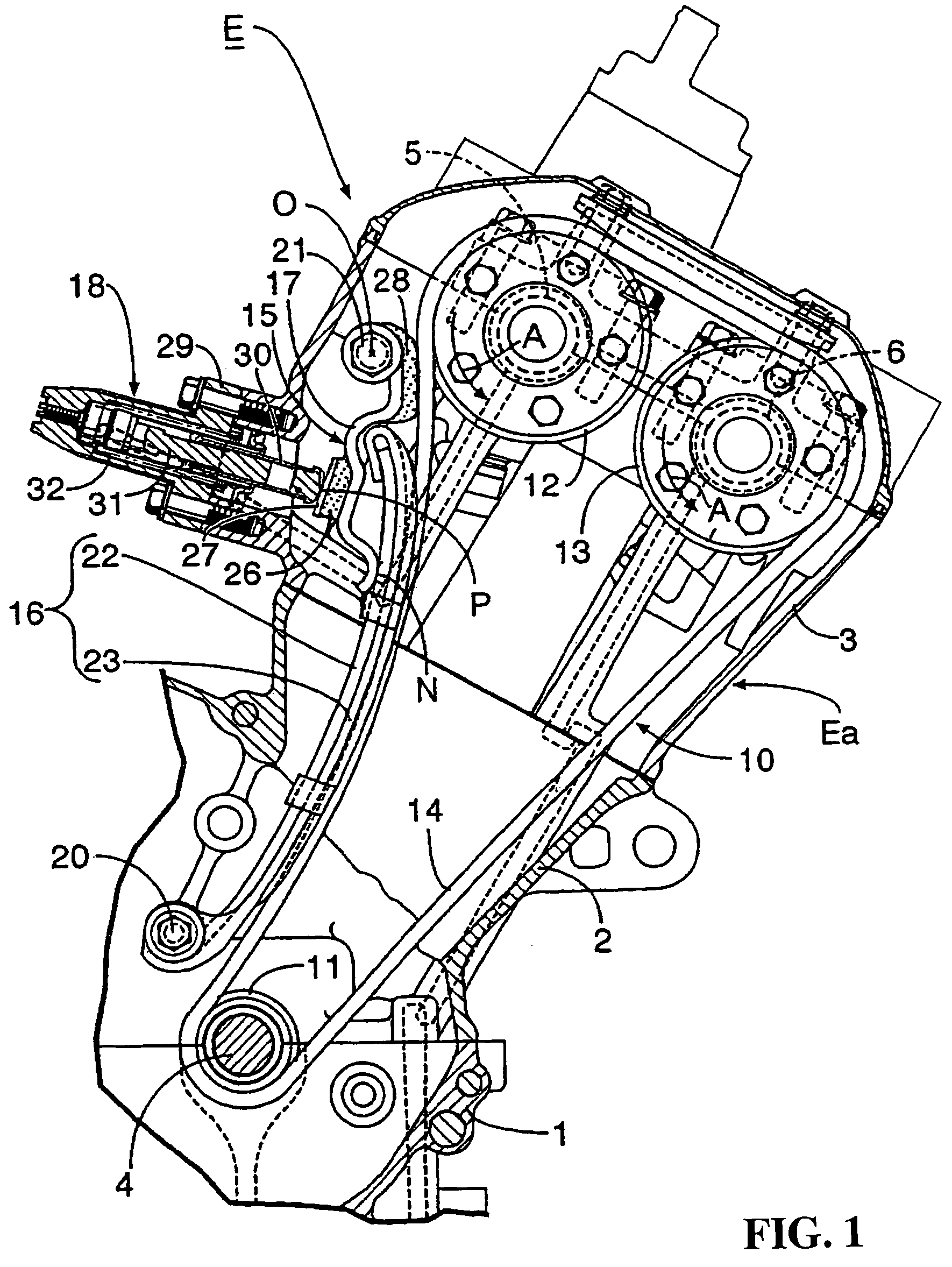
[0034]First, as shown in FIG. 1, an engine E for a motorcycle is arranged in a state in which the head is inclined in front of a vehicle. The body Ea of the engine E is composed of a crankcase 1, a cylinder block 2 and a cylinder head 3, a crankshaft 4 is supported by the crankcase 1, a camshaft for intake air 5 and a camshaft for exhaust 6 are supported by the cylinder head 3, and the crankshaft 4, the camshaft for intake air 5 and the camshaft for exhaust 6 are coupled by a timing transmission gear 10.

[0035]The timing transmission gear 10 is composed of a driving sprocket 11 fixed to the crankshaft 4, first and second driven sprockets 12, 13, respectively, are fixed to the camshaft for intake air 5. The camshaft for exhaust 6 and a transmission chain 14, without an end wound on the driving sprocket 11, is fixed to the first and second driven sprockets 12, 13. The first and second driv...


PUM


Abstract

To enable the simultaneous achievement of the enhancement of an oscillation absorption function of a tensioner arm for a transmission chain and the enhancement of wear resistance in a chain tensioner. A tensioner arm is composed of an elastic band tensioner arm body curved toward a transmission chain and a flexible tensioner shoe which covers the front of the tensioner arm body and which is provided with a chain guide groove to the front of which the transmission chain is slidably fitted. The width of the middle in the longitudinal direction of the tensioner arm body is set so that the width is smaller than the width of each end of the arm body.

Description

CROSS-REFERENCE TO RELATED APPLICATIONS[0001]The present application claims priority under 35 USC 119 to Japanese Patent Application No. 2002-265193 filed on Sep. 11, 2002 the entire contents thereof are hereby incorporated by reference.BACKGROUND OF THE INVENTION[0002]1. Field of the Invention[0003]The present invention relates to a chain tensioner provided with a tensioner arm rockably supported by a fixed structure and relatively slidably engaged with the outside on the loose side of a transmission chain without an end coupling a driving sprocket and a driven sprocket and a tensioner lifter supported by fixed structure for pressing the tensioner arm upon the side of the transmission chain. More particularly, the invention relates to the improvement of a chain tensioner the tensioner arm which is formed by a band elastic member curved toward the transmission chain.[0004]2. Description of Background Art[0005]In such a chain tensioner, it is already well-known as disclosed in Japane...

Claims


Application Information

Patent Timeline
IPC IPC(8): F16H7/08
CPCF16H7/0848F16H2007/0804F16H2007/0872F16H2007/0859F16H2007/0812
Inventor SONOBATA, AKIRA
Owner HONDA MOTOR CO LTD
Learn More