Modular system for spinal column fusion

a module system and spinal column technology, applied in bone implants, prostheses, medical science, etc., can solve the problems of plurality of implants, loss of height in the affected disk space, and impairment of the nerve roots in this region and/or the spinal marrow, so as to reduce the number of implant bodies to be kept in stock

Inactive Publication Date: 2006-03-28
TUTOGEN MEDICAL INC
View PDF21 Cites 94 Cited by
  • Summary
  • Abstract
  • Description
  • Claims
  • Application Information

AI Technical Summary

Benefits of technology

[0008]It is the object of the invention to further develop such a spinal implant such that the demands initially

Problems solved by technology

The degeneration of the intervertebral disk, in particular of the nucleus pulposus, results in a loss of height in the affected disk space which is associated with a weakening of the annulus fibrosus and of the ligaments.
The consequence is a horizontal displaceability of the vertebral bodies with respect to one another which results in impai

Method used


Image

  • Modular system for spinal column fusion
  • Modular system for spinal column fusion
  • Modular system for spinal column fusion

Examples


Embodiment Construction

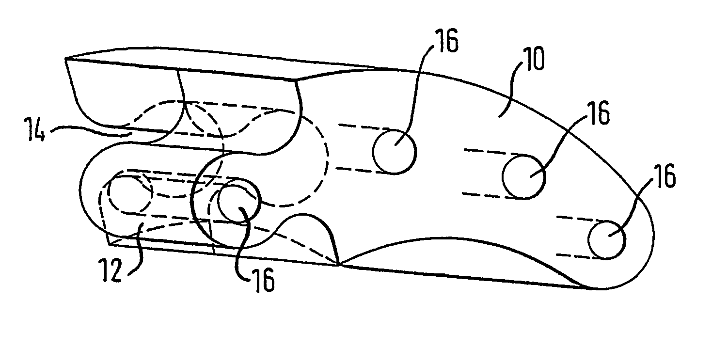
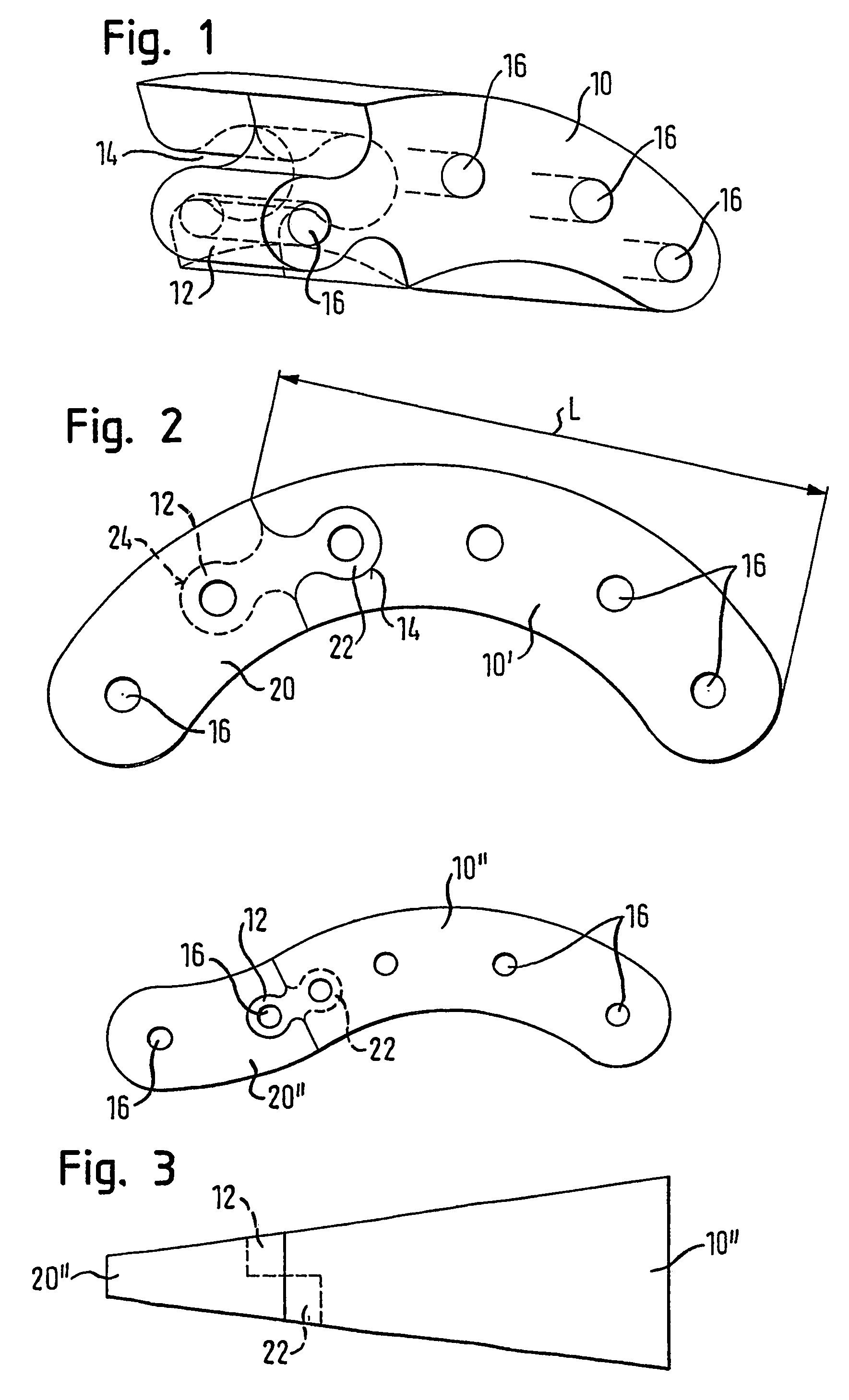
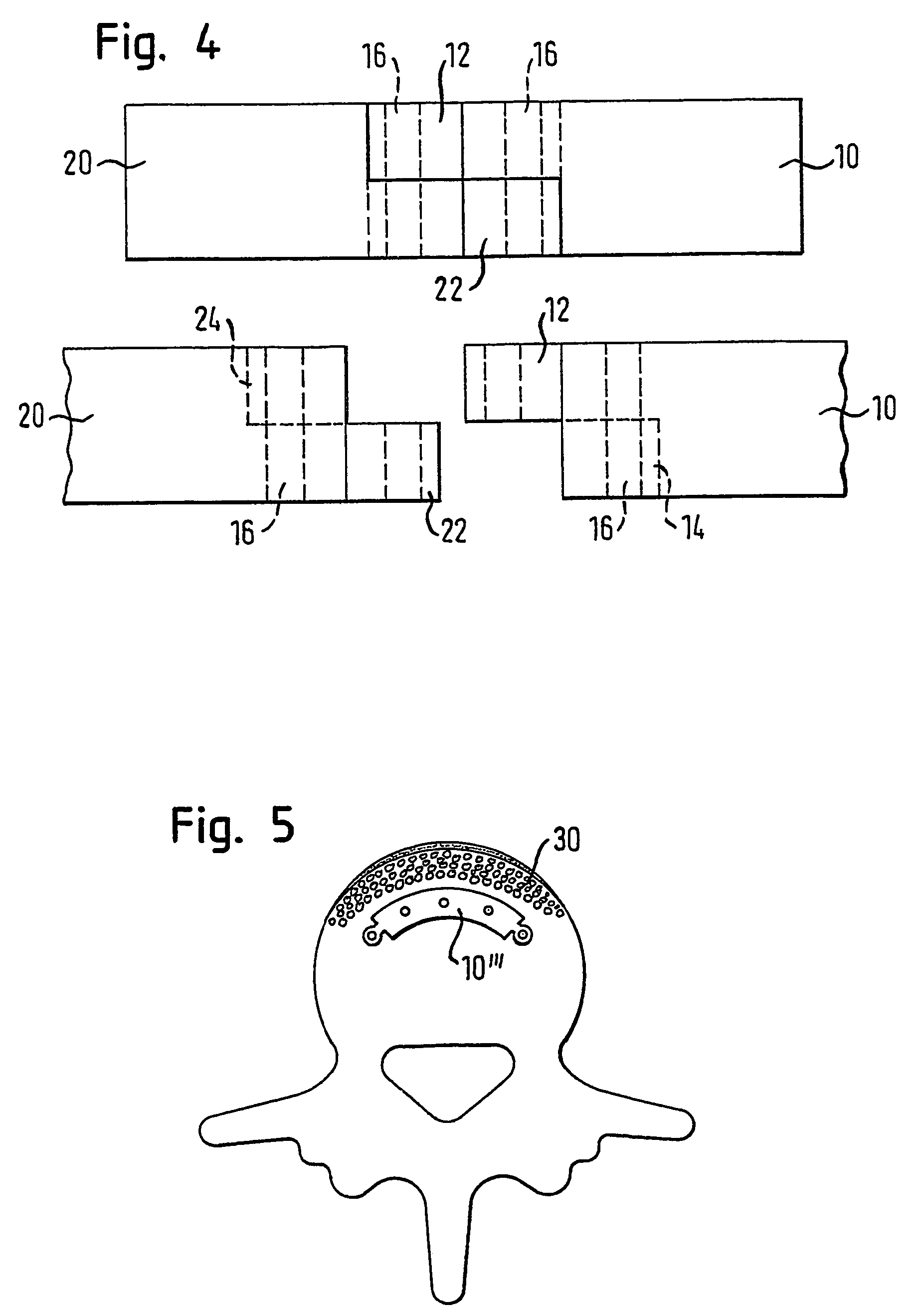
[0032]FIG. 1 shows a perspective, schematic view of a spinal implant in accordance with the invention for interbody fusion to the spinal column which consists of a body or base body 10 made of bone material which is generally elongate and is curved in the direction of its longitudinal extent. The base body is cut out of a sufficiently thick bone of human or animal origin as a ring segment, with the width of the ring segment having to amount to at least 4 mm and the outer radius of the ring segment having to amount to at least 12 mm. The height of the segment or of the base body can lie between 6 and 18 mm.

[0033]As FIG. 1 shows, two coupling means are provided in the form of a projection 12 and of a cut-out 14 at the end of the base body 10 at the left in FIG. 1. Both the height of the projection 12 and the height of the cut-out 14 amount to half the height of the base body 10. The projection 12 is spigot-like and is connected to the base body 10 in one piece. The shape of the projec...


PUM


Abstract

The invention relates to a spinal implant consisting of a bone material body which is embodied in a curved manner in its longitudinal direction and is provided with coupling means.

Description

RELATED APPLICATIONS[0001]This application is the U.S. National Phase of PCT Application PCT / EP02 / 09602 filed Aug. 28, 2002, which claims priority of German Application DE 101 52 567.2 filed Oct. 24, 2001, the contents of which are herein incorporated by reference.FIELD OF THE INVENTION[0002]The present invention relates to a spinal implant for interbody fusion to the spinal column.BACKGROUND OF THE INVENTION[0003]The degeneration of the intervertebral disk, in particular of the nucleus pulposus, results in a loss of height in the affected disk space which is associated with a weakening of the annulus fibrosus and of the ligaments. The spinal column hereby becomes instable at this position. The consequence is a horizontal displaceability of the vertebral bodies with respect to one another which results in impairments of the nerve roots in this region and / or of the spinal marrow with pain resulting therefrom.[0004]The principle for the treatment of these symptoms consists of the surg...

Claims


Application Information

Patent Timeline
IPC IPC(8): A61F2/44A61F2/00A61F2/28A61F2/30
CPCA61F2/4455A61F2/28A61F2310/00359A61F2002/2817A61F2002/30131A61F2002/30133A61F2002/30135A61F2002/30324A61F2002/30383A61F2002/30387A61F2002/30604A61F2002/30616A61F2002/30785A61F2002/448A61F2220/0025A61F2230/0004A61F2230/0013A61F2230/0015A61F2250/0036A61F2002/30136A61F2/44
Inventor KRUGER, MANFRED
Owner TUTOGEN MEDICAL INC
Why Eureka
Try Eureka