Method and apparatus for removing contaminants from conduits and fluid columns

a technology of conduits and fluid columns, applied in electrochemical methods, electrostatic separators, electrochemical methods, etc., can solve the problems of less resistance within, achieve the effect of reducing the incidence of surface contact, increasing the effectiveness of contaminant separation electrodes, and enhancing contaminant separation

Inactive Publication Date: 2006-03-28
WILSA HLDG
View PDF7 Cites 9 Cited by
  • Summary
  • Abstract
  • Description
  • Claims
  • Application Information

AI Technical Summary

Benefits of technology

[0016]This invention generally relates to the treatment of fluid columns with an emphasis on the prevention of contaminant deposition, the removal of deposits from the internal walls of conduits and the extraction of contaminants from a fluid column. Therefore, treatment of feedstocks with a magnetic field generator typically enhances the ability of a fluid to flow through conduits and equipment utilized in the storage, transportation and delivery of a fluid.
[0047]Utilizing a magnetic field generator to pretreat a fluid column and place elements within a feed stream in suspension typically increases the effectiveness of the contaminant separation electrodes of the instant invention. Magnetic fluid treatment typically retards the accumulation of contaminants as deposits on electrode plates by inducing similar charges to the elements carried within a feedstock. By subjecting a feed stream to an intense magnetic field, dissolved substances within the fluid column tend to remain in suspension due to their decreased incidence of surface contact and bonding as a result of similarly charged ions repelling each other as they pass through the reactor instead of forming adhesive deposits that could otherwise coat electrodes and impede their efficiency. Thus, magnetic treatment of a feedstock typically prevents clogging and restricted flow within a contaminant separation reactor by placing elements within a feed stream in suspension and impeding the formation of deposits on electrodes that could diminish the effective generation of electrical charges between the electrically charged plates.

Problems solved by technology

Further, air-cooling the device results in less resistance within the continuous coil of wire, allowing more current to flow through the wire coil.

Method used


Image

  • Method and apparatus for removing contaminants from conduits and fluid columns
  • Method and apparatus for removing contaminants from conduits and fluid columns
  • Method and apparatus for removing contaminants from conduits and fluid columns

Examples


first embodiment

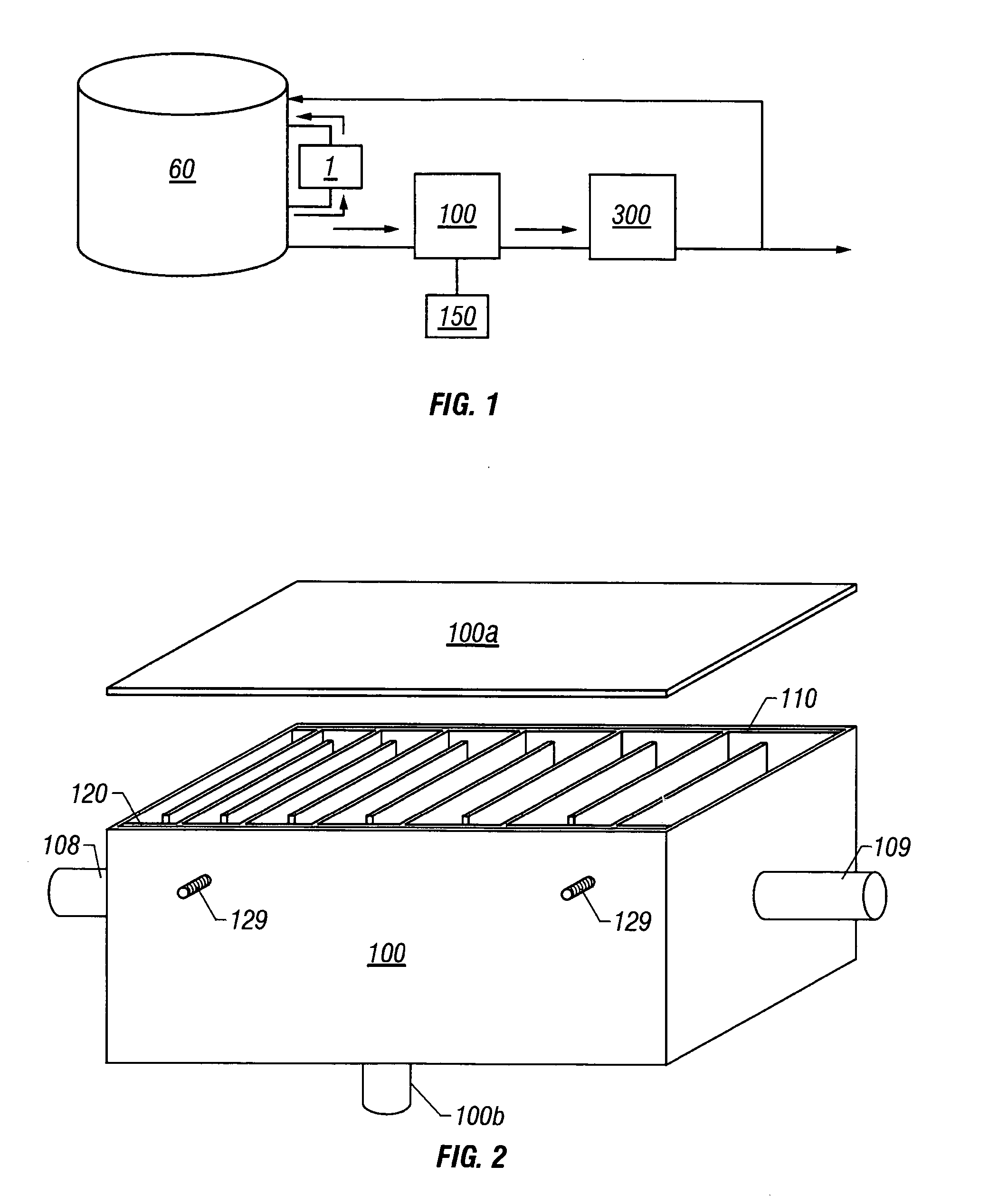
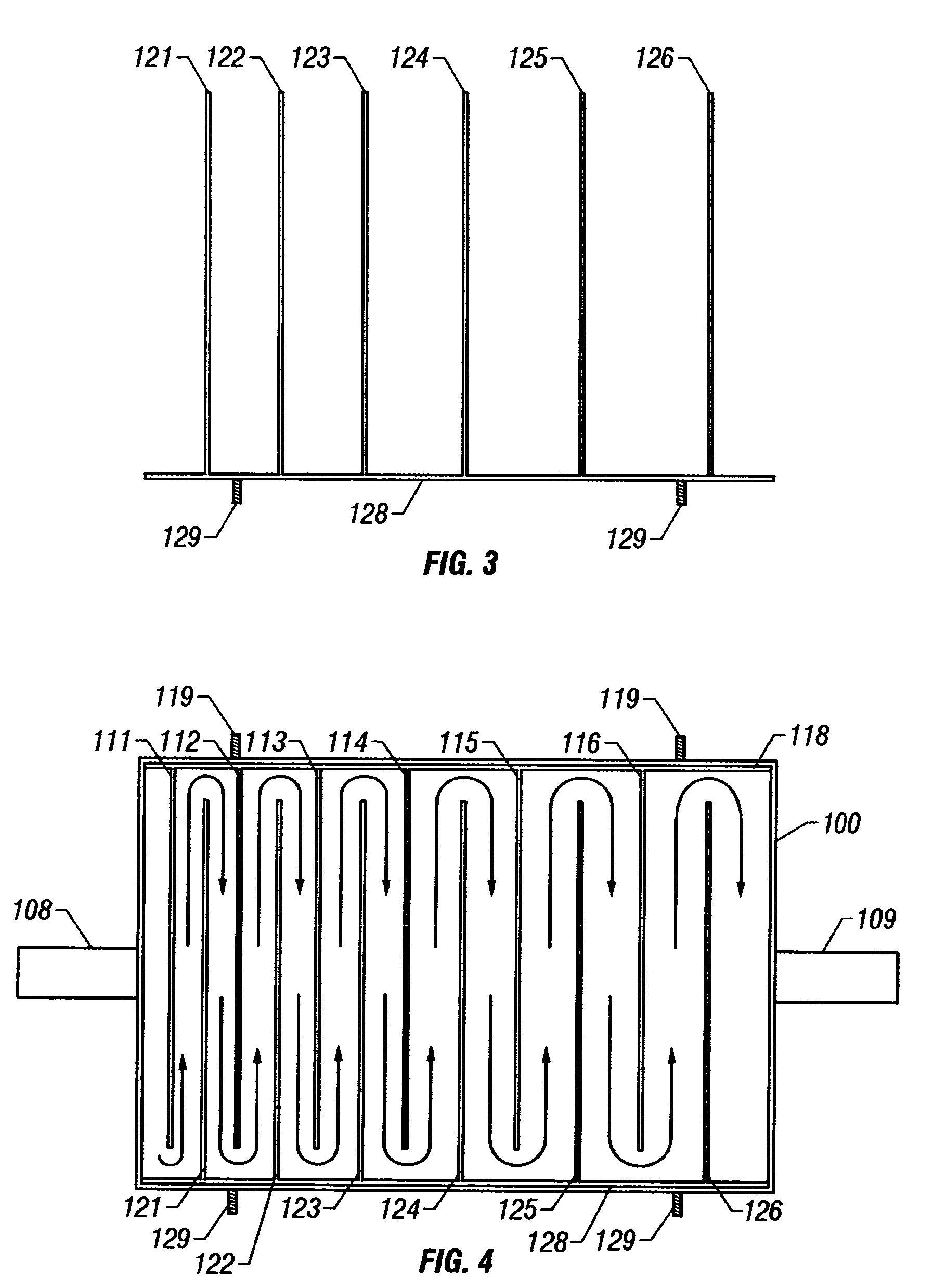
[0073]FIG. 2 depicts an open top view of the contaminant separation reactor of the instant invention. Opposing electrodes 110 and 120 are shown within reactor housing 100 defining an interior chamber established by a fluid impervious boundary wall with an inner surface and having inlet and outlet ports. Each electrode is comprised of a plurality of parallel, spaced apart plates of an electrically conductive material coupled to a common buss bar wherein the cavities between the plates are non-uniform and the plates are fixed in a perpendicular orientation to the buss bar. The electrode plates are arranged in a parallel pattern that provides for progressively greater distances between the facing surfaces of each adjacent plate. The plates of the opposing electrodes interleave in a parallel orientation to define a flow path from the inlet port to the outlet port and form a series of cavities of non-uniform volume. As such, the flow path of a fluid is substantially orthogonal to the dir...

second embodiment

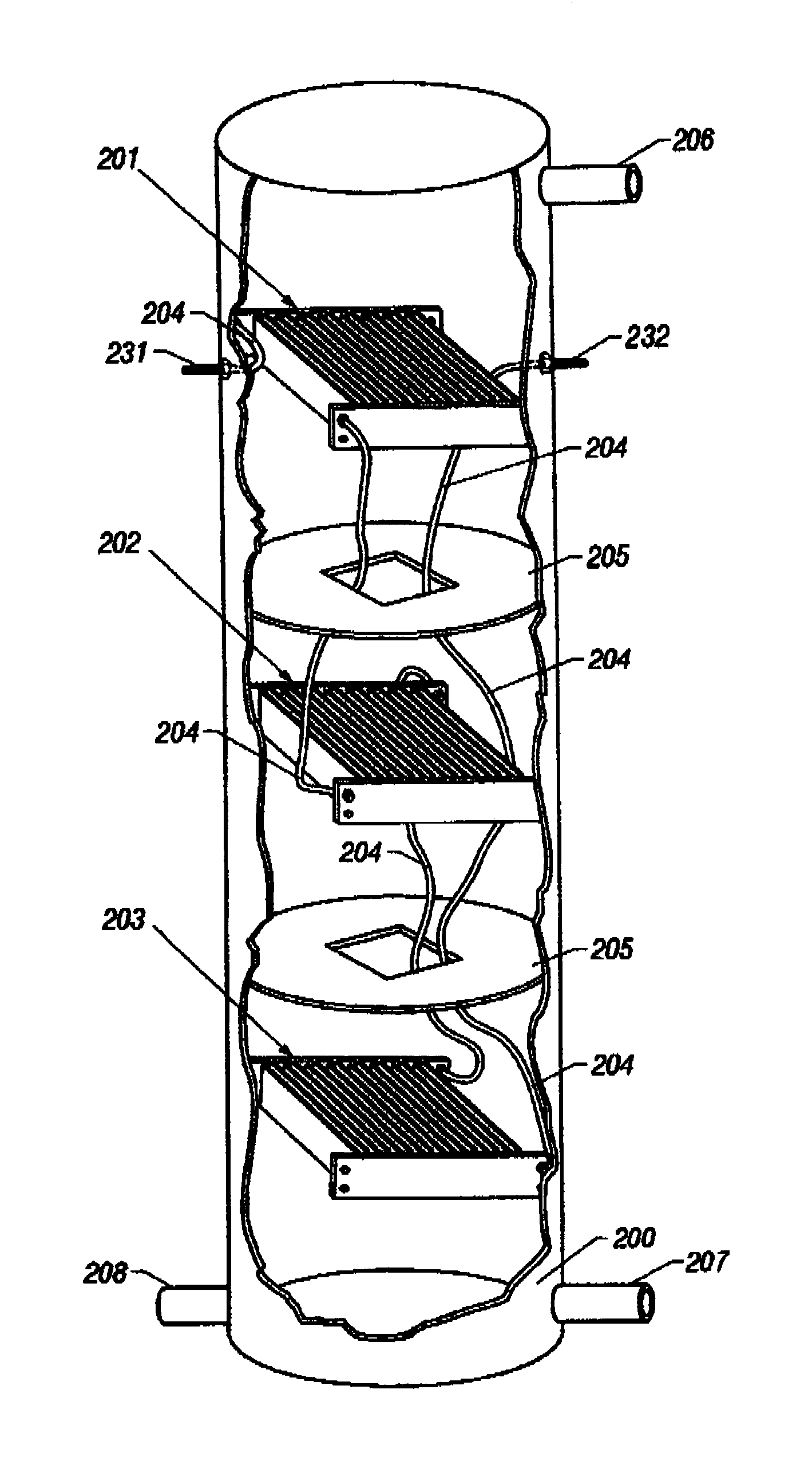
[0085]FIG. 5 is a top view of a contaminant separation sector utilized in the contaminant separation reactor of the instant invention. As used herein, a contaminant separation sector shall mean a distinct fluid treatment unit comprising a pair of electrodes, each electrode comprising a plurality of parallel, spaced-apart plates of an electrically conductive material coupled to a common buss bar wherein the spacing between the plates of each contaminant separation sector is uniform. Plates 221, 223, 225 and 227 are typically comprised of an electrically conductive material having a uniform thickness, length and height and fixed as a parallel array to buss bar 229. Plates 222, 224, 226 and 228 are typically comprised of an identical electrically conductive material having a uniform thickness, length and height and fixed as a parallel array to buss bar 230.

[0086]Buss bar 229 facilitates the flow of electricity to the parallel array of plates 221, 223, 225 and 227 while buss bar 230 fac...


PUM

PropertyMeasurementUnit
lengthaaaaaaaaaa
lengthaaaaaaaaaa
lengthaaaaaaaaaa

Abstract

A method and apparatus for contaminant separation utilizes an interleaved array of oppositely charged electrode plates for fluid treatment. Spacing between the parallel electrode plates is graduated so that the volume of the cavities between the opposing electrodes provides varying levels of treatment of a broad range of contaminants from a variety of fluid columns. A fluid flow path extending substantially orthogonal to the direction of the electrical field established between opposing electrode plates provides a feed stream with exposure to the varying levels of electrical charges between the electrode plates. The method and apparatus provide an effective means of contaminant separation by a device having a small footprint and requiring low amounts of electrical energy.

Description

BACKGROUND OF THE INVENTION[0001]The present invention relates to extraction of scale, corrosion, deposits and contaminants from within conduits and on equipment utilized in the transmission of fluid columns, and further relates to the removal of contaminants that may accumulate within fluid columns transferred in such conduits.[0002]It is common for contaminant deposits to accumulate within the inner walls of conduits and equipment utilized in the transportation and transmission of fluids from one location to another. In oilfield pipelines, for example, a mixture of oil, water and minerals may flow out of a well and through equipment used to separate the marketable oil from the water and other components of the fluid column. Paraffin, asphaltene and mineral scale deposits typically form in conduits used to transport this fluid mixture and restrict flow within the pipeline. These deposits and the associated congestion they create may further lead to the deterioration of pumps, valve...

Claims


Application Information

Patent Timeline
Patent Type & Authority Patents(United States)
IPC IPC(8): C02F1/461C02F1/00C02F1/46C02F1/463C02F1/48C02F9/00
CPCC02F1/46109C02F1/48C02F1/4602C02F1/4606C02F2305/023C02F2303/22C02F1/463C02F1/484C02F9/00C02F2001/46123C02F2001/46133C02F2103/023C02F2201/4611C02F2201/4613C02F2201/483C02F2301/024C02F2303/04C02F1/461
Inventor HOLLAND, HERBERT W.
Owner WILSA HLDG
Why Eureka
Try Eureka