Method of transferring a protective overcoat to a dye-donor element

a technology of dye-donor elements and protective overcoats, applied in diffusion transfer processes, instruments, nuclear engineering, etc., can solve the problems of inability to eliminate these problems, reduce the gloss of laminated prints, and inability to eliminate them. , to achieve the effect of improving increasing the gloss of the print, and improving the effect of the

Inactive Publication Date: 2006-03-28
EASTMAN KODAK CO
View PDF6 Cites 6 Cited by
  • Summary
  • Abstract
  • Description
  • Claims
  • Application Information

AI Technical Summary

Benefits of technology

[0009]By use of the present process, a dye-donor element is provided containing a transferable protection layer that is capable of giving a higher gloss to an image after transfer.
[0010]In particular, predesigned adjustment of the time between applying the protection layer to a thermal print and then peeling them apart has been found to provide increased gloss to the print. A means for stripping the portion of protection overcoat (adhered to the thermally printed receiver by the thermal-print head) from the rest of the dye-donor element provides improved results especially at faster print times. The time of peeling can be adjusted by the relative position of the means for stripping, such as a stripper plate, relative to the print head or other parts of the thermal printer.
[0011]Increased gloss of a glossy print is an advantage in the physical quality of the print. This is particularly advantageous at lower line times, faster printing. In one embodiment, the method of the invention employed with respect to a protection overcoat transferred from the fourth patch laminate of a thermal donor results in a higher gloss on the print after the laminate has been transferred to the receiver when compared to the control with current methods.

Problems solved by technology

Thermal prints are susceptible to retransfer of dyes to adjacent surfaces and to discoloration by fingerprints.
This will help to reduce dye retransfer and fingerprint susceptibility, but does not eliminate these problems.
It has been found that the gloss on a laminated print decreases as the printing line time decreases, which is a problem as printing times become faster.

Method used


Image

  • Method of transferring a protective overcoat to a dye-donor element
  • Method of transferring a protective overcoat to a dye-donor element
  • Method of transferring a protective overcoat to a dye-donor element

Examples


examples

Printing

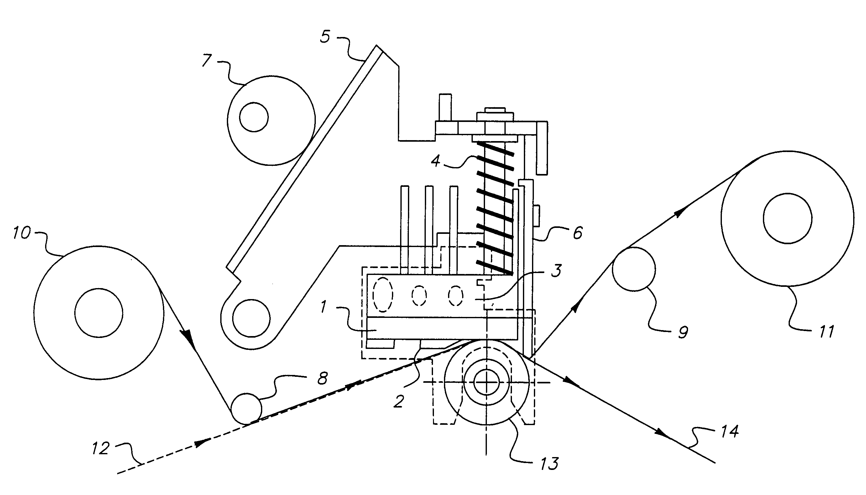
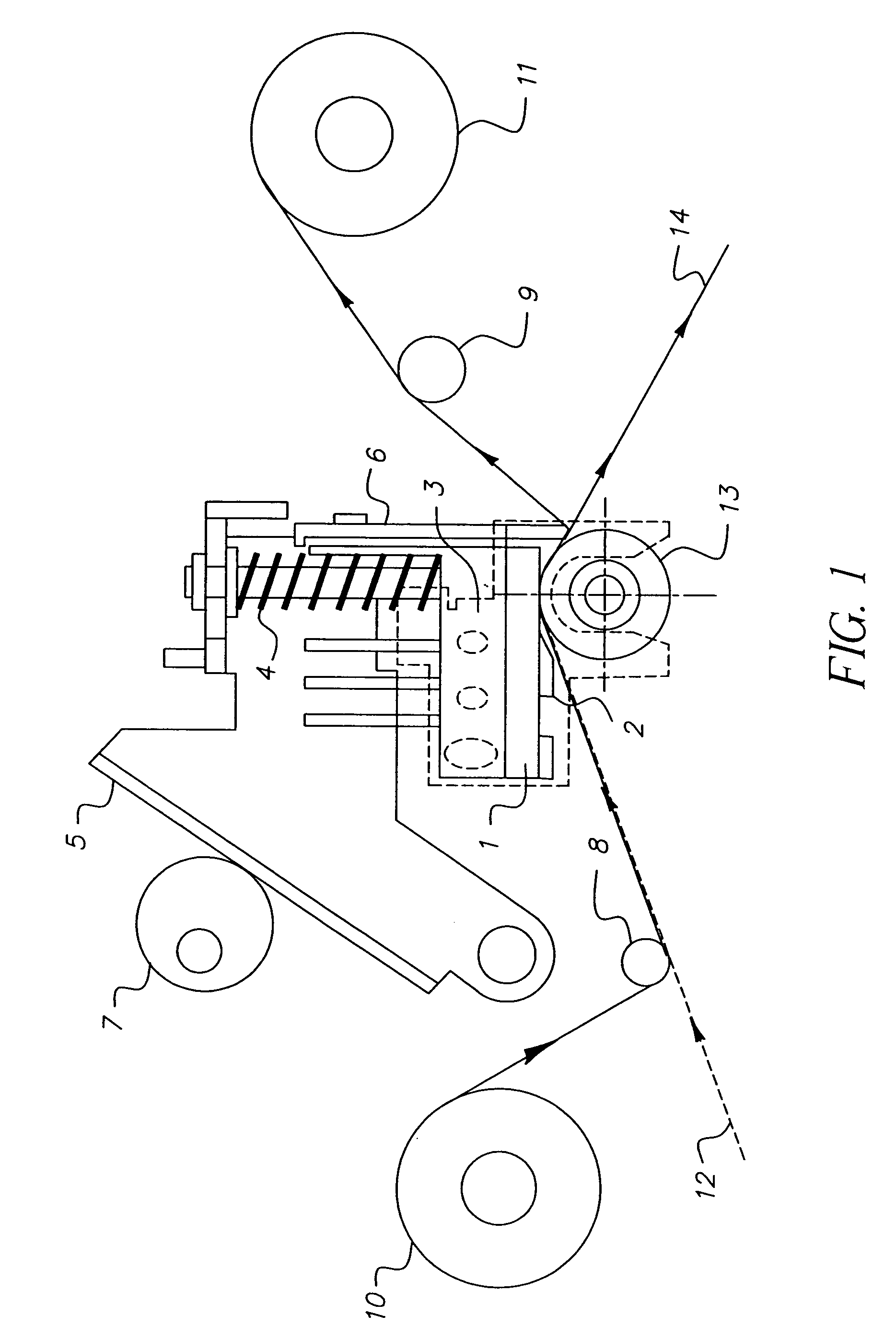
[0071]This example shows improved gloss from adjustment of stripper plate assembly according to the present invention. Using KODAK Photo Printer® Kit 6400 (Eastman Kodak Co. Catalog No. 180-2016) receiver with the test color ribbon given below and a KODAK Photo Printer® 6400, a Status A neutral density image with a maximum density of at least 2.3 was printed on the receiver described above.

[0072]The color ribbon-receiver assemblage was positioned on an 18 mm platen roller and a thermal print head with a load of 3.18 Kg pressed against the platen roller. The thermal print head has 1844 independently addressable heaters with a resolution of 300 dots / inch and an average resistance of 4800 ohms. The imaging electronics were activated when an initial print head temperature of 37° C. had been reached. The assemblage was drawn between the printing head and platen roller at 70.5 mm / sec (1.2 ms line time) for yellow, magenta and cyan, 42 mm / sec (2.0 ms line time) for clear protective...


PUM

PropertyMeasurementUnit
timeaaaaaaaaaa
timeaaaaaaaaaa
timeaaaaaaaaaa

Abstract

This invention relates to a method for transferring a protective overcoat for a thermal print wherein the protective overcoat is applied to a dye-donor element under predesigned conditions after thermal dye transfer, the dye-donor element comprising patches of dye for transfer to a thermal print to provide a protective layer thereon. In particular, the invention improves the process of providing an improved level of gloss to the transferred protective overcoat. The method involves a preselected duration between printing and peeling the transferable laminate patch, respectively, to and from the donor. The invention is particularly advantageous at lower line times, faster printing, for thermal prints with high gloss.

Description

FIELD OF THE INVENTION[0001]This invention relates to a method for transferring a protective overcoat for a thermal print wherein the protective overcoat is applied to a dye-donor element under predesigned conditions after thermal dye transfer, the dye-donor element comprising patches of dyes for transfer to a thermal print to provide a protective layer thereon. In particular, the invention improves the process of providing an improved level of gloss to the transferred protective overcoat.BACKGROUND OF THE INVENTION[0002]In recent years, thermal transfer systems have been developed to obtain prints from pictures that have been generated electronically from a color camera. According to one way of obtaining such prints, an electronic picture is first subjected to color separation by color filters. The respective color-separated images are then converted into electrical signals. These signals are then operated on to produce cyan, magenta and yellow signals. These signals are then trans...

Claims


Application Information

Patent Timeline
Patent Type & Authority Patents(United States)
IPC IPC(8): B41M7/00G03C11/08G03C11/10B41M5/382
CPCB41M5/38207B41M7/0027Y10S430/162B41M5/38221B41M5/38264
Inventor SIMPSON, WILLIAM H.MINDLER, ROBERT F.HASTREITER, JACOB J.
Owner EASTMAN KODAK CO
Why Eureka
Try Eureka