Brushless DC motor with tray coupling structure

a dc motor and coupling structure technology, applied in the direction of structural association, dynamo-electric machines, instruments, etc., can solve the problems of inability to adjust the rotational balance, excessive grinding adversely affects the strength and rotational stability of the tray, and the grinding procedure takes a long time. , to achieve the effect of reliable loading of an optical disc and flexible adjustment of the rotational balan

Inactive Publication Date: 2006-03-28
SUNONWEALTH ELECTRIC MACHINE IND
View PDF16 Cites 24 Cited by
  • Summary
  • Abstract
  • Description
  • Claims
  • Application Information

AI Technical Summary

Benefits of technology

[0007]An object of the present invention is to provide a brushless DC motor with a tray coupling structure that provides assembling convenience, flexible adjustment in rotational balance, and reliable loading of an optical disc.

Problems solved by technology

However, the grinding procedure takes a long time, and repetitious tests are required during the grinding procedure.
Further, excessive grinding adversely affects the strength and rotational stability of the tray 15.
However, adjustment in rotational balance is impossible.
Further, as miniaturization is a trend of spindle motors, it would be impossible for the top face of the rotor having a relatively small area to bear an optical disc.

Method used


Image

  • Brushless DC motor with tray coupling structure
  • Brushless DC motor with tray coupling structure
  • Brushless DC motor with tray coupling structure

Examples


first embodiment

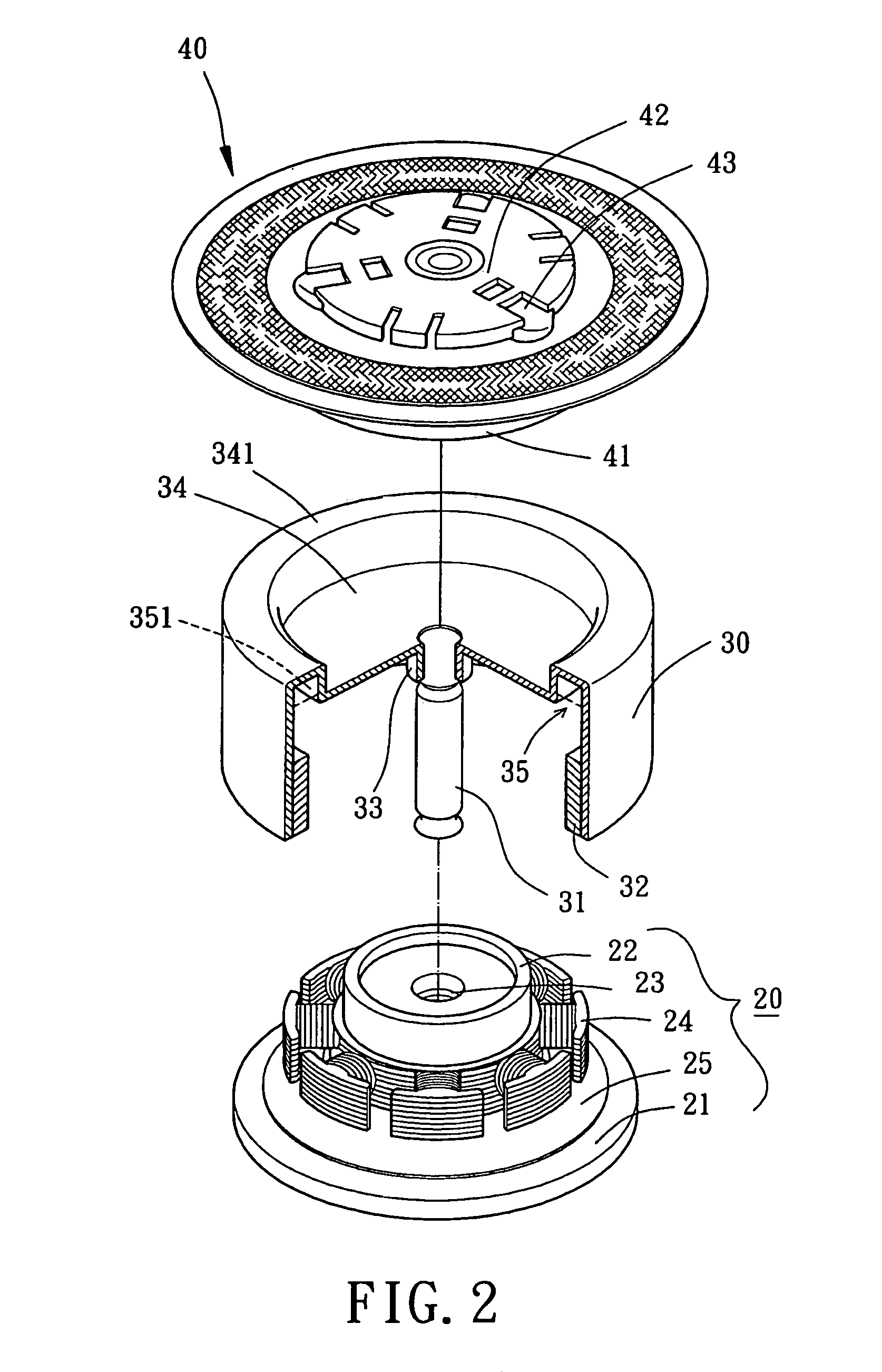
[0026]Referring to FIGS. 2 and 3, a brushless DC motor in accordance with the present invention comprises a fixed portion 20, a rotor 30, and a tray 40. The fixed portion 20 includes a base 21, an axial tube 22, a bearing 23, a stator 24, and a circuit board 25. The base 21 can be fixed in a casing of an optical disc drive (not shown). The axial tube 22 is fixed on or integrally formed with the base 21. At least one bearing 23 (one in this embodiment) is mounted in the axial tube 22. The stator 24 and the circuit board 25 are mounted around the axial tube 22. The bearing 23 may be an oily bearing, a ball bearing, a fluid dynamic bearing, or a magnetic bearing. The stator 24 may include radial winding or axial winding. The circuit board 25 includes a control circuit. The circuit board 25 may be integrally formed with the base 21. When the control circuit of the circuit board 25 is powered, the stator 24 is controlled to create an alternating magnetic field.

[0027]Still referring to FI...

fourth embodiment

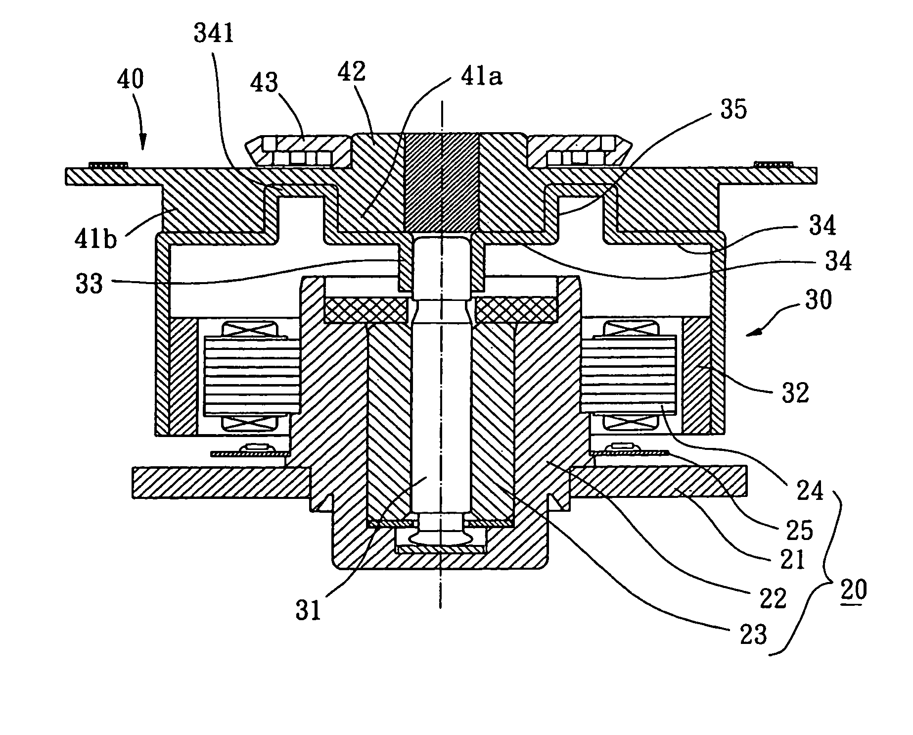
[0034]FIG. 6 shows the invention, wherein the top engaging face 34 includes a central annular protruded engaging portion 341b located on the central portion of the top engaging face 34 and in contact with the axial seat 33. The top engaging face 34 further includes a peripheral annular protruded engaging portion 341a located along a peripheral portion of the top engaging face 34. Preferably, the central annular protruded engaging portion 341a is integrally formed with the axial seat 33. The peripheral annular protruded engaging portion 341a and the central annular protruded engaging portion 341b together define an annular engaging space (not labeled) for coupling with the tray 40.

[0035]The tray 40 includes a complementary engaging portion 41 that is engaged with an outer periphery of the central annular protruded engaging portion 341b and an inner periphery of the peripheral annular protruded engaging portion 341a by fitting engagement or glue and that is in contact with the top eng...


PUM


Abstract

A brushless DC motor includes a fixed portion and a rotor. The rotor includes a shaft and a top engaging face. The shaft is rotatably held by the fixed portion. The top engaging face is located on a top side of the rotor. The rotor further includes at least one protruded engaging portion on the top engaging face. A carrier such as a tray or the like is fixedly coupled with the at least one protruded engaging portion. A compartment is defined in the rotor by the at least one protruded engaging portion. A filling material may be filled into the compartment for adjusting rotational balance of the rotor.

Description

BACKGROUND OF THE INVENTION[0001]1. Field of the Invention[0002]The present invention relates to a brushless DC motor. In particular, the present invention relates to a brushless DC motor with a tray coupling structure.[0003]2. Description of Related Art[0004]FIG. 1 illustrates a conventional brushless DC motor for an optical disc that is disclosed in, e.g., Taiwan Utility Model Publication Nos. 456667 and 590329, and U.S. Pat. No. 6,815,852. Such a brushless DC motor comprises a fixed base 11, a bearing 12, a stator 13, a rotor 14, and a tray 15. The fixed base 11 includes a control circuit and an axial tube 111 in a central portion thereof for receiving the bearing 12 and for supporting the stator 13. The stator 13 is controlled by the control circuit on the fixed base 11 and creates an alternating magnetic field. The rotor 14 includes a shaft 141 rotatably held by the bearing 12 and an annular magnet 142 for induction with the alternating magnetic field to drive the rotor 14 to t...

Claims


Application Information

Patent Timeline
Patent Type & Authority Patents(United States)
IPC IPC(8): H02K5/24
CPCG11B19/2009G11B19/2027H02K15/165H02K5/1675H02K7/04H02K1/2786H02K1/2791
Inventor HORNG, ALEXCHEN, ARTHUR
Owner SUNONWEALTH ELECTRIC MACHINE IND
Why Eureka
Try Eureka