Diffraction grating element, production method of diffraction grating element, and method of designing diffraction grating element

a technology of diffraction grating and grating elements, which is applied in the direction of instruments, coatings, optics, etc., can solve the problems of reducing the polarization dependence of diffraction efficiency and improving diffraction efficiency in a wide wavelength band

Active Publication Date: 2006-03-28
SUMITOMO ELECTRIC IND LTD
View PDF10 Cites 17 Cited by
  • Summary
  • Abstract
  • Description
  • Claims
  • Application Information

AI Technical Summary

Benefits of technology

[0009]It is possible to reduce the difference in the diffraction efficiency between the TE polarized light and the TM polarized light, by appropriately designing the sectional configuration (height, width or like of the grating) of the diffraction grating so that the polarization dependence due to the reflection and the polarization dependence due to the structure are canceled. However, even when so designed as described above, it is impossible to improve the diffraction efficiency and reduce the polarization dependence of the diffraction efficiency in a wide wavelength band.
[0029]A designing method of the diffraction grating element of the present invention is a designing method of a diffraction grating element having a diffraction grating portion of which index of refraction changes periodically in a predetermined direction and a reflection-inhibiting portion on at least one of the top and the bottom of the diffraction grating portion, comprising the steps of determining so that each of the diffraction grating portion and the reflection-inhibiting portion is formed with a film having an average index of refraction by the media included therein respectively, setting the phase change of light at the diffraction grating portion to 90°, and deriving refraction distribution of the diffraction grating element so that the reflectance is 10% or less at a desired wavelength. According to the designing method of the diffraction grating element, result of analysis can be obtained close to the characteristics of an actually produced diffraction grating element. Accordingly, the diffraction grating element can be designed easily.

Problems solved by technology

However, even when so designed as described above, it is impossible to improve the diffraction efficiency and reduce the polarization dependence of the diffraction efficiency in a wide wavelength band.

Method used


Image

  • Diffraction grating element, production method of diffraction grating element, and method of designing diffraction grating element
  • Diffraction grating element, production method of diffraction grating element, and method of designing diffraction grating element
  • Diffraction grating element, production method of diffraction grating element, and method of designing diffraction grating element

Examples


first embodiment

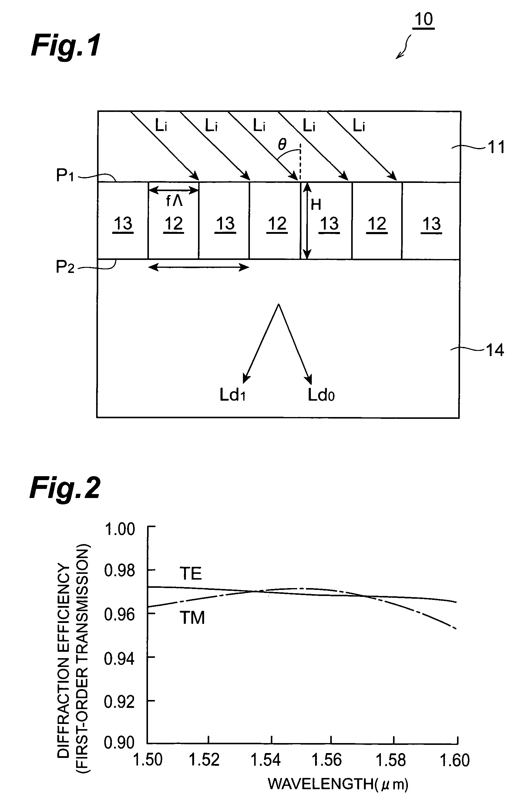
[0053]First of all, a first embodiment of a diffraction grating element in accordance with the present invention will be described. FIG. 1 is an explanatory diagram of a diffraction grating element 10 in accordance with the first embodiment. The diagram shows a section of the diffraction grating element 10 when the same is cut off at a plane perpendicular to the grating. The diffraction grating element 10 shown in the diagram comprises a first medium 11, a second medium 12, a third medium 13 and a fourth medium 14.

[0054]In this diffraction grating element 10, a first plane P1 and a second plane P2, which are parallel to each other, are assumed. Here, the first medium 11 is provided at the outer side than the first plane P1 (upper side in the diagram) being in contact with the first plane P1. Between the first plane P1 and the second plane P2, the second medium 12 and the third medium 13 are disposed alternately in a predetermined direction parallel to the first plane P1 being in con...

second embodiment

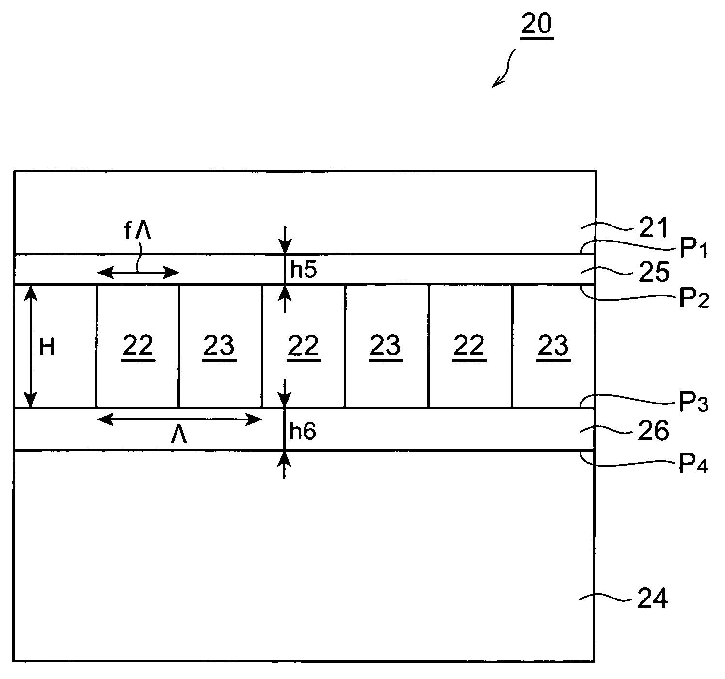
[0077]Next, a second embodiment of a diffraction grating element in accordance with the present invention will be described. FIG. 7 is an explanatory diagram of a diffraction grating element 20 in accordance with a second embodiment. The diagram shows a section of the diffraction grating element 20 when the same is cut off at a plane perpendicular to the grating. The diffraction grating element 20 shown in the diagram comprises a first medium 21, a second medium 22, a third medium 23, a fourth medium 24, a fifth medium 25 and a sixth medium 26.

[0078]In this diffraction grating element 20, a first plane P1, a second plane P2, a third plane P3 and fourth plane P4, which are parallel to each other and aligned in order, are assumed. Here, the first medium 21 is provided at the outer side than the first plane P1 (upper side in the diagram) being in contact with the first plane P1. Between the second plane P2 and the third plane P3, the second medium 22 and the third medium 23 are dispose...

third embodiment

[0099]Next, a third embodiment of a diffraction grating element in accordance with the present invention will be described. FIG. 12 is an explanatory diagram of a diffraction grating element 30 in accordance with the third embodiment. The diagram shows a section of the diffraction grating element 30 when the same is cut off at a plane perpendicular to the grating. The diffraction grating element 30 shown in the diagram comprises a first medium 31, a second medium 32, a third medium 33, a fourth medium 34, and a fifth medium 35.

[0100]In the diffraction grating element 30, a first plane P1, a second plane P2 and a third plane P3, which are parallel to each other and aligned in order, are assumed. Here, the first medium 31 is provided at the outer side than the first plane P1 (upper side in the diagram) being in contact with the first plane P1. Between the second plane P2 and the third plane P3, the second medium 32 and the third medium 33 are disposed alternately in a predetermined di...


PUM

PropertyMeasurementUnit
diffraction angleaaaaaaaaaa
thicknessaaaaaaaaaa
reflectanceaaaaaaaaaa

Abstract

In a diffraction grating element 10, between a first medium 11 and a fourth medium 14, a second medium 12 and a third medium 13 are disposed alternately to form a diffraction grating. The light, which enters the diffraction grating from the first medium 11, is diffracted at the diffraction grating portion and output to a fourth medium 14. Or, the light, which enters the diffraction grating from the fourth medium 14, is diffracted at the diffraction grating portion and output to the first medium 11. The index of refraction n1–n4 of each medium satisfies a relational expression of “n3<n1<n2, n3≦n4≦n2” or “n3≦n1≦n2, n3<n4<n2”.

Description

RELATED APPLICATIONS[0001]This application claims priority to Provisional Application Ser. No. 60 / 447710 filed on Feb. 19, 2003, which is hereby incorporated by reference in its entirety.BACKGROUND OF THE INVENTION[0002]1. Field of the Invention[0003]The present invention relates to a transmission diffraction grating element, a production method of diffraction grating element and a method of designing diffraction grating element.[0004]2. Related Background of the Invention[0005]Generally, a diffraction grating element is, in a transparent flat plate having a first plane and a second plane parallel to each other, formed with a diffraction grating on the first plane (see Kashiko Kodate, “Development of diffractive optics and future challenges”; Japan Women's University Journal, Faculty of Science, 10th Edition, pages 7 to 24 (2002), for example). In the diffraction grating element, for example, when light enters the first plane from a medium, which is in contact with the first plane, ...

Claims


Application Information

Patent Timeline
Patent Type & Authority Patents(United States)
IPC IPC(8): G02B5/18
CPCG02B1/11G02B5/1857G02B5/1814
Inventor SHIOZAKI, MANABUSHIGEHARA, MASAKAZU
Owner SUMITOMO ELECTRIC IND LTD
Why Eureka
Try Eureka