
Method and apparatus for reducing transmitter peak power requirements using dual matrices

a technology of peak power requirements and matrices, applied in the field of communication systems, can solve the problems of transmitters and particularly higher-power transmitters, particularly power amplifiers (pas), being subject to abuse, transmitters or power amplifiers are subject to or often experience relatively higher failure rates than some system components

Active Publication Date: 2006-03-28
GOOGLE TECH HLDG LLC
View PDF11 Cites 29 Cited by
  • Summary
  • Abstract
  • Description
  • Claims
  • Application Information

AI Technical Summary

Benefits of technology

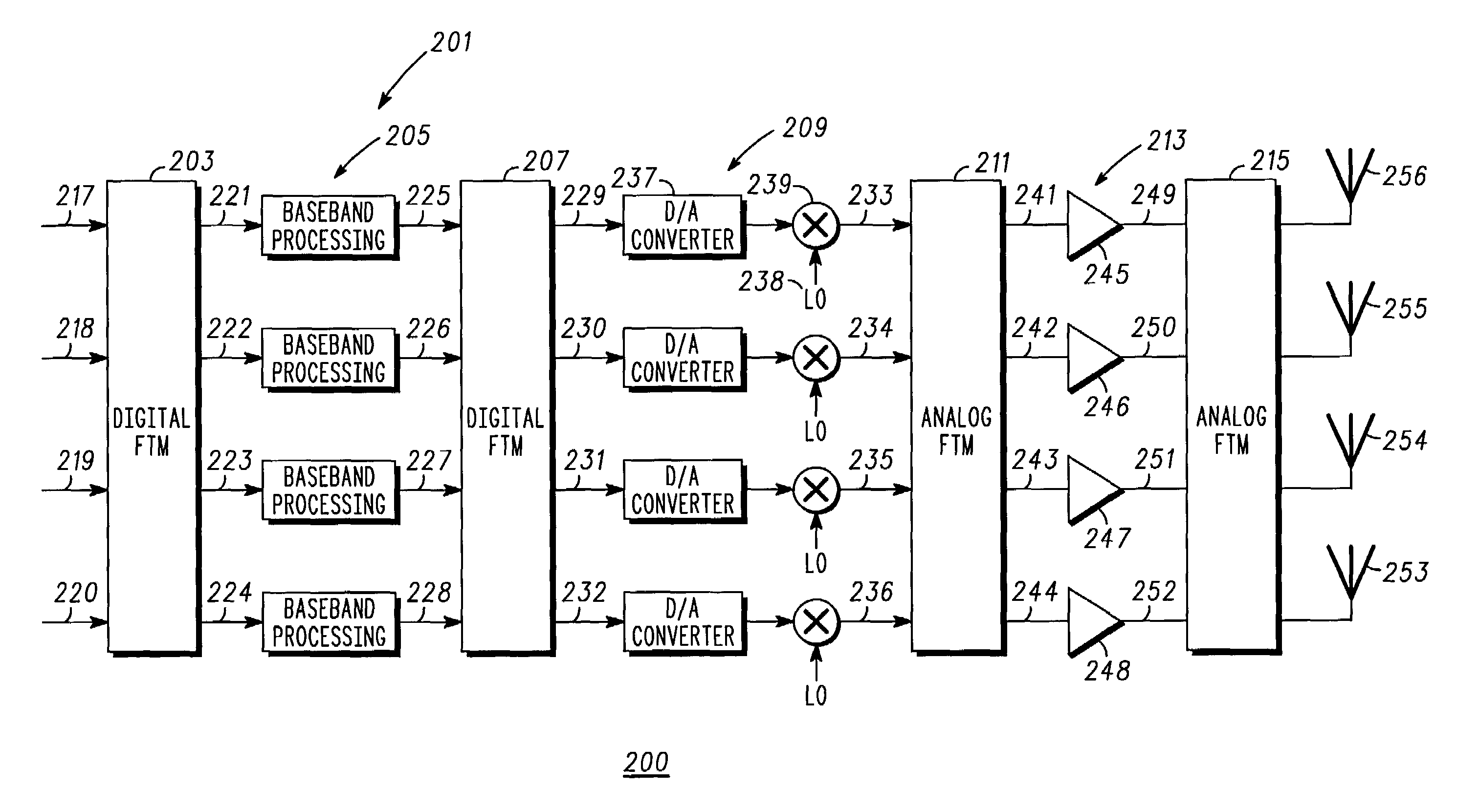
[0046]As a summary and in the context of the methodology that we have discussed with reference to the apparatus figures the following description of a preferred method is provided. We have discussed and described a method of reducing peak power requirements in a multi-channel transmitter. This method includes coupling at least one input signals to a Fourier Transform Matrix (FTM), preferably a digital FTM, to provide a plurality of FTM output signals each comprising a combination of phase shifted versions of the one or more input signals. Then the method processes the plurality of FTM output signals by limiting a peak value for each of the FTM output signals to provide a plurality of peak limited output signals, then decomposes the peak limited output signals to provide one or more output base band signals, each of the output base band signals corresponding to one of the input signals and then converts the output base band signals from a base band frequency to a transmission radio frequency to provide a plurality of radio frequency signals. From there the process generates a plurality of amplifier input signals, each comprising a combination of phase shifted versions of the one or more radio frequency signals, where the amplifier input signals, preferably, correspond to the peak limited output signals. Next, the method amplifies the amplifier signals to provide a plurality of amplified output signals using a power amplifier having a plurality of amplifiers, each amplifier having an input coupled to one of the plurality of the radio frequency signals and providing one of the amplified output signals. Thereafter decomposing the plurality of amplified output signals to provide at least one and preferably a plurality of transmit signals corresponding one to one with the output base band signals is undertaken.

Problems solved by technology

Transmitters and particularly higher power transmitters, specifically power amplifiers (PAs), are one of the more expensive and more highly stressed, from a power perspective, components of a communications system.
By virtue of the PAs relatively intimate coupling to an antenna system they are subject to abuse due, for example, to antenna irregularities, such as mismatches and weather or lightning events.
For these reasons transmitters or power amplifiers are subject to or often experience relatively higher failure rates than some system components.
Therefore carriers or service providers or network operators cannot afford to have a transmitter failure and will go to great lengths to avoid failures or at least service outages when there is a failure.
However, there is still a problem.
Many communications systems today require linear PAs because they rely on complex modulation schemes that specify amplitude and phase variations in the transmitted radio signals.
Linear PAs are very difficult and expensive to construct.
In conventional amplifier systems there are known techniques for processing the input signals to assist with these goals, however there are no known techniques that work when FTMs are employed.

Method used


Image

  • Method and apparatus for reducing transmitter peak power requirements using dual matrices
  • Method and apparatus for reducing transmitter peak power requirements using dual matrices
  • Method and apparatus for reducing transmitter peak power requirements using dual matrices

Examples


Embodiment Construction

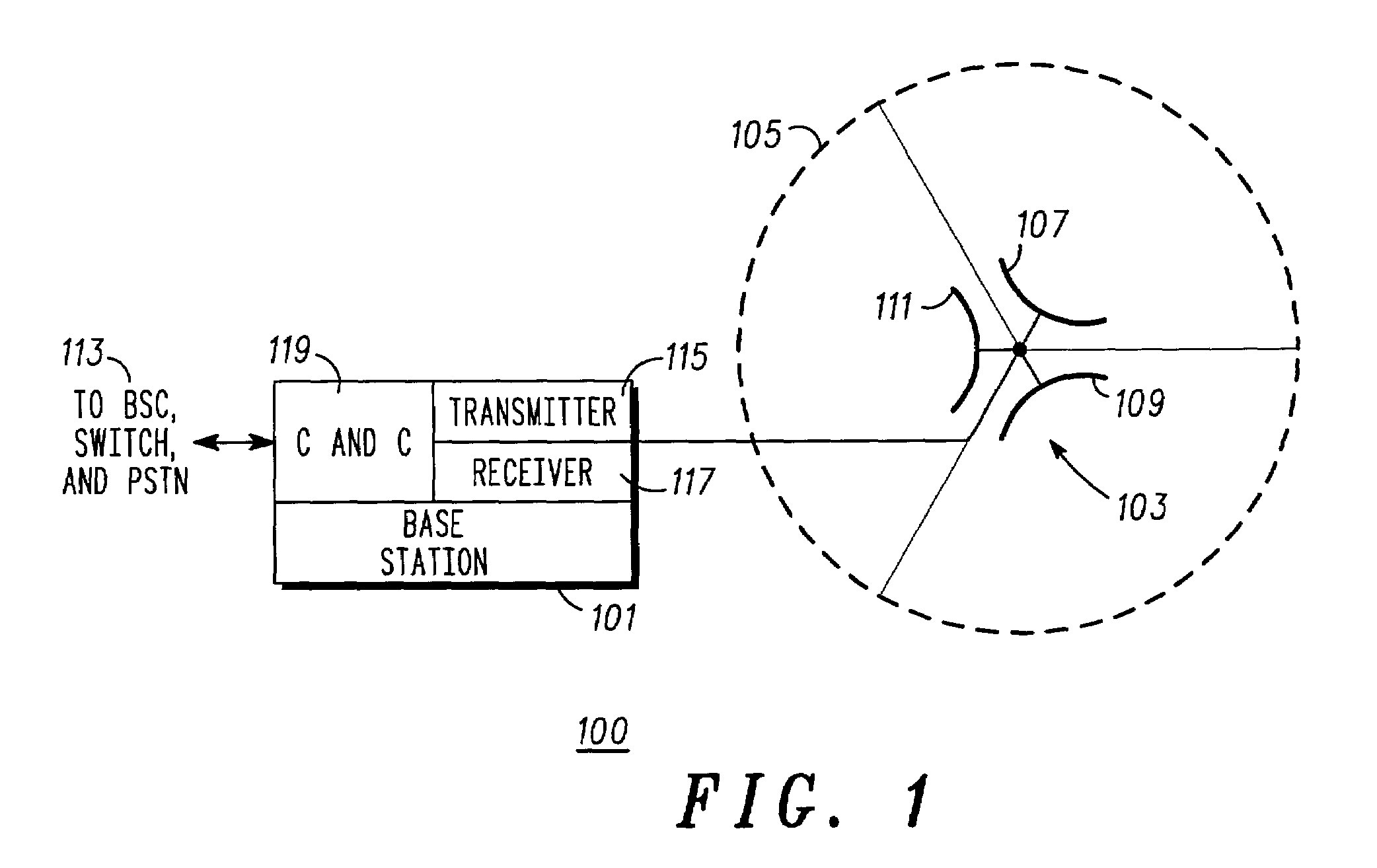
[0012]In overview form the present disclosure concerns communications systems that utilize transmitters to provide service to communications units or more specifically user thereof operating therein. More particularly various inventive concepts and principles embodied in methods and apparatus for the reduction of peak power requirements for transmitters are discussed and disclosed. The communications systems of particular interest are those being deployed and developed such as GSM, GPRS, EDGE, TETRA, iDEN, CDMA, W-CDMA, CDMA2000, 2.5G, or 3G systems that use modulation formats such as QPSK, DQPSK, OQPSK, BPSK, QAM, and spread spectrum or variations and evolutions thereof that require cost effective high availability linear transmitters.

[0013]As further discussed below various inventive principles and combinations thereof are advantageously employed to essentially construct and process at base band the signals that the amplifiers will encounter, thus alleviating various problems asso...


PUM


Abstract

An apparatus and method thereof for processing base band signals to reduce peak power requirements for a multi-channel transmitter is disclosed. The apparatus includes a first Fourier Transform Matrix (FTM) coupled to one or more input signals for providing a plurality of output signals; a processing unit for limiting a peak value for each of the output signals, and a second FTM for decomposing the peak limited output signals to provide one or more output base band signals, each of the output base band signals corresponding to one of the input signals. A multi-channel transmitter further converts the output base band signals to a radio frequency signals; a first analog FTM provides a plurality of amplifier input signals; a power amplifier having a plurality of amplifiers provides a plurality of amplified output signals; and a second analog FTM coupled to the amplified output signals provides transmit signals corresponding one to one with the output base band signals.

Description

FIELD OF THE INVENTION[0001]This invention relates in general to communication systems, and more specifically to a method and apparatus for reducing peak power requirements in transmitters within such systems using Transform Matrices.BACKGROUND OF THE INVENTION[0002]Communications systems and particularly wireless communications systems require transmitters in one form or another. Transmitters and particularly higher power transmitters, specifically power amplifiers (PAs), are one of the more expensive and more highly stressed, from a power perspective, components of a communications system. By virtue of the PAs relatively intimate coupling to an antenna system they are subject to abuse due, for example, to antenna irregularities, such as mismatches and weather or lightning events. For these reasons transmitters or power amplifiers are subject to or often experience relatively higher failure rates than some system components. These higher power transmitters are typically found in ba...

Claims


Application Information

Patent Timeline
IPC IPC(8): H04L25/03H04L5/06H04L27/26
CPCH04L5/06H04L27/2614H04L25/03H03F3/60
Inventor PORCO, RONALD L.GREENWOOD, WILLIAM C.FRANSON, GLEN A.
Owner GOOGLE TECH HLDG LLC
Learn More