Method and design for electrical stress mitigation in high voltage insulators in X-ray tubes

a high-voltage insulator and x-ray tube technology, which is applied in the direction of x-ray tube electrodes, electrical equipment, electric discharge tubes, etc., can solve the problems of x-ray tube failure x-ray tube life expectancy to be affected, etc., and achieve the effect of reducing electrical stresses

Inactive Publication Date: 2006-03-28
GENERAL ELECTRIC CO
View PDF8 Cites 10 Cited by
  • Summary
  • Abstract
  • Description
  • Claims
  • Application Information

AI Technical Summary

Benefits of technology

[0007]Briefly in accordance with one embodiment, the present technique provides an X-ray tube. The X-ray tube includes an anode assembly configured to emit X-ray beams and a cathode assembly configured to emit electrons towards the anode assembly. The cathode assembly includes an insulator and a cathode post. The insulator includes a side surface, wherein the...

Problems solved by technology

The X-ray system may operate at high voltages and temperatures, which affect the life expectancy of the X-ray tube.
As such, the temperatures and voltages involved with the operation of the X-ray tube may affect the life expectancy of the X-ray tube.
Because of the voltages and temperatures involved, various problems may occur that cause the X-ray tube to fail.
The failures may include electrical stresses, such as high voltage instabilities, surface flashovers, and other insul...

Method used


Image

  • Method and design for electrical stress mitigation in high voltage insulators in X-ray tubes
  • Method and design for electrical stress mitigation in high voltage insulators in X-ray tubes
  • Method and design for electrical stress mitigation in high voltage insulators in X-ray tubes

Examples


Embodiment Construction

[0017]As a preliminary matter, the definition of the term “or” for the purpose of the following discussion and the appended claims is intended to be an inclusive “or.” That is, the term “or” is not intended to differentiate between two mutually exclusive alternatives. Rather, the term “or” when employed as a conjunction between two elements is defined as including one element by itself, the other element itself, and combinations and permutations of the elements. For example, a discussion or recitation employing the terminology “A” or “B” includes: “A”, by itself “B” by itself and any combination thereof, such as “AB” and / or “BA.”

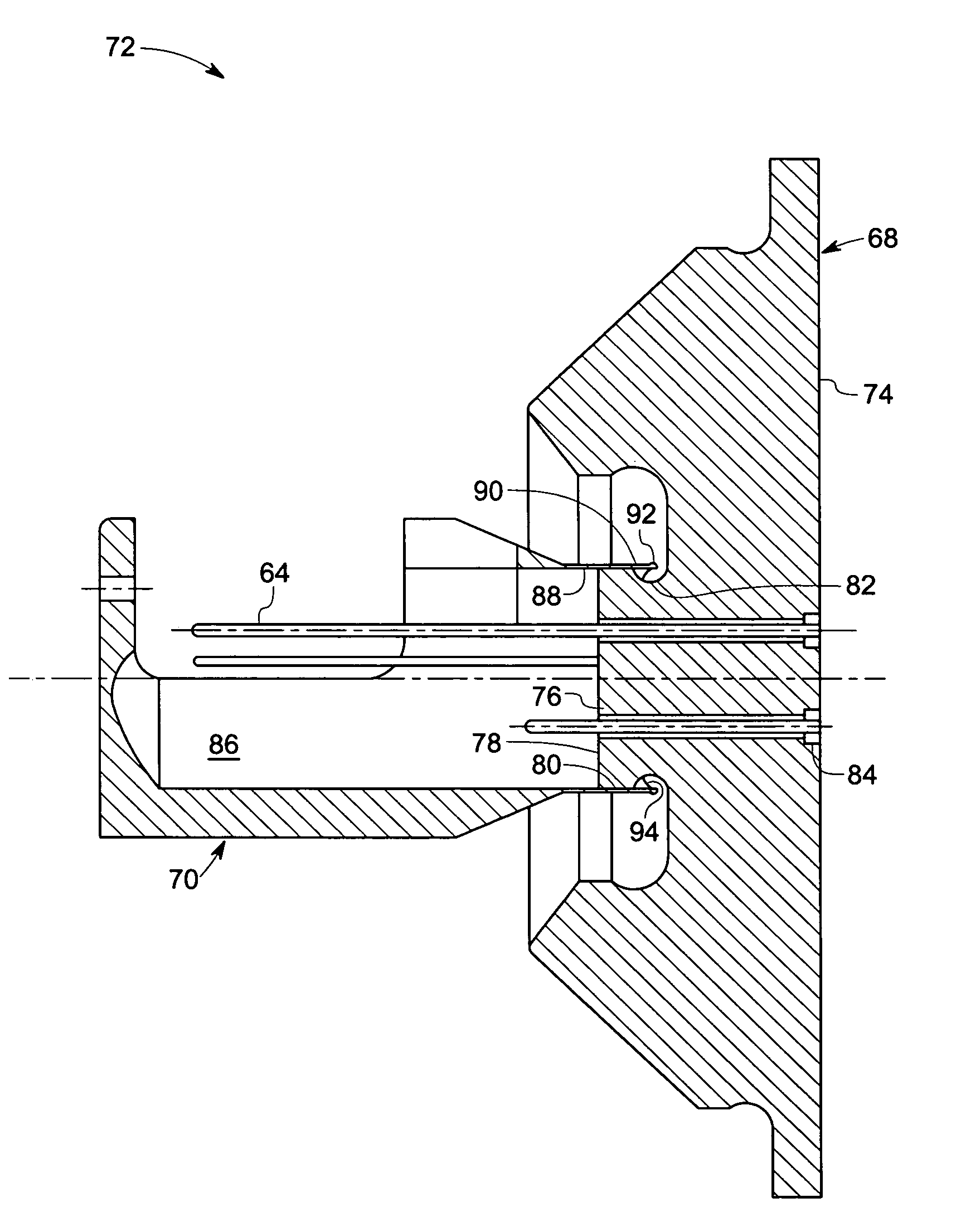
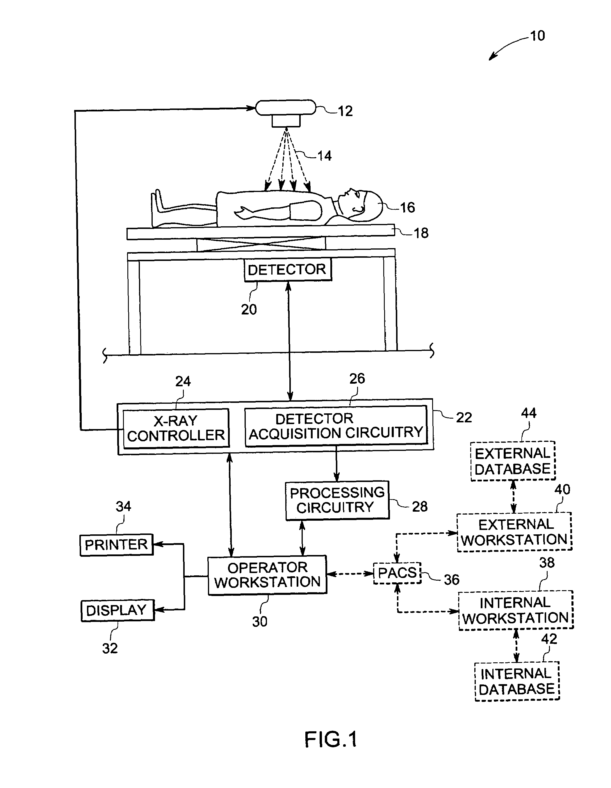
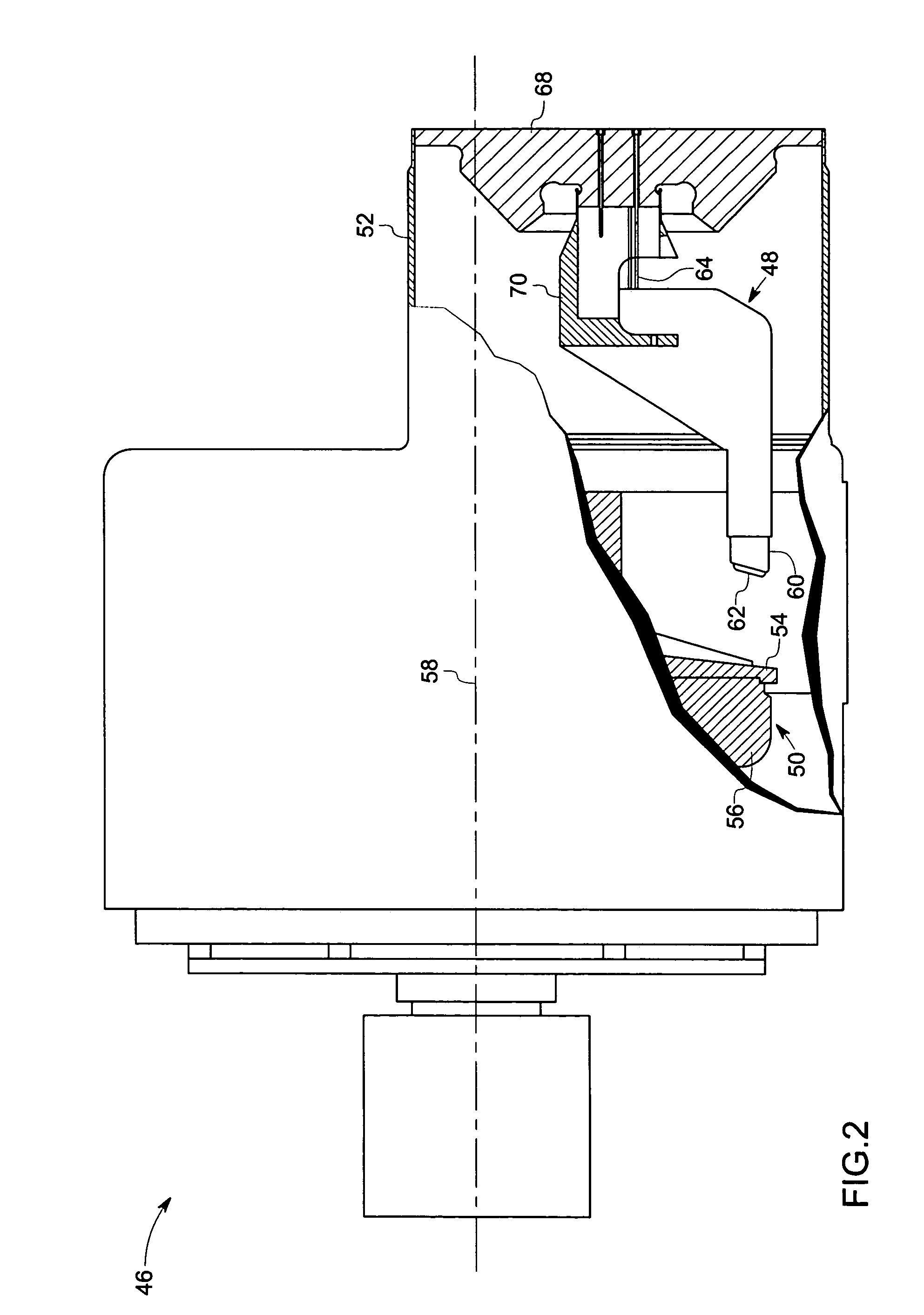
[0018]The present technique is generally directed towards managing electrical stresses in an X-ray tube for high voltage applications. As will be appreciated by those of ordinary skill in the art, the present techniques may be applied in various medical and non-medical applications. To facilitate the explanation of the present techniques, however, a medical ...


PUM


Abstract

In accordance with one embodiment, the present technique provides an X-ray tube. The X-ray tube includes an anode assembly configured to emit X-ray beams and a cathode assembly configured to emit electrons towards the anode assembly. The cathode assembly includes an insulator and a cathode post. The insulator includes a side surface, wherein the side surface includes a recessed portion. The cathode post includes a hollow interior region having an interior surface, wherein the interior surface is configured to engage with the side surface of the insulator. The cathode post may also include a foot portion that extends away from the interior surface at the end of the cathode post. The cathode post adjacent to the recessed portion of the insulator is configured to shield a triple point to reduce electrical stresses on the triple point.

Description

BACKGROUND[0001]The present invention relates generally to a system for managing electrical stresses in an X-ray tube for high voltage applications and, more specifically, to a cathode assembly with a high-voltage insulator that manages electrical stresses at its triple point.[0002]X-ray systems are generally utilized in various applications for imaging in the medical and non-medical fields. For example, X-ray systems, such as radiographic systems, computed tomography (CT) systems, and tomosynthesis systems, are used to create internal images or views of a patient based on the attenuation of X-ray beams passing through the patient. Based on the X-ray beams, a profile of the patient is created. Alternatively, X-ray systems may also be utilized to in non-medical applications, such as detecting minute flaws in equipment or structures and / or scanning baggage at airports.[0003]Typically, the X-ray system includes an X-ray tube that is utilized as the source of X-ray beams directed to a d...

Claims


Application Information

Patent Timeline
IPC IPC(8): H01J35/00
CPCH01J35/06H01J35/064
Inventor WILSON, COLIN RICHARDCAO, YANGROFFERS, RICHARD MICHAELARNOTT, CLAIRE ALEXANDRAHUNT, IAN STRIDER
Owner GENERAL ELECTRIC CO
Why Eureka
Try Eureka