Method and device for determining position

a position and measurement device technology, applied in the field of position determination, can solve the problems of low number of lines between the position measuring device and the sequential electronic device, relatively susceptible to interference and noise, and low accuracy of position measurement results

Inactive Publication Date: 2006-03-28
DR JOHANNES HEIDENHAIN GMBH
View PDF8 Cites 3 Cited by
  • Summary
  • Abstract
  • Description
  • Claims
  • Application Information

AI Technical Summary

Benefits of technology

[0020]A reduced number of signal lines between the position measuring device and the sequential electronic device can be realized by the present invention. Six signal lines or less are sufficient, namely two for the clock pulse, two for the voltage supply and two for the measured values (data). The clock pulse can also be transmitted over the lines for voltage supply.

Problems solved by technology

However, the transmission of analog position measuring values is relatively susceptible to interference and noise, and the high number of lines between the position measuring device and the sequential electronic device is also negative.

Method used


Image

  • Method and device for determining position
  • Method and device for determining position
  • Method and device for determining position

Examples


Embodiment Construction

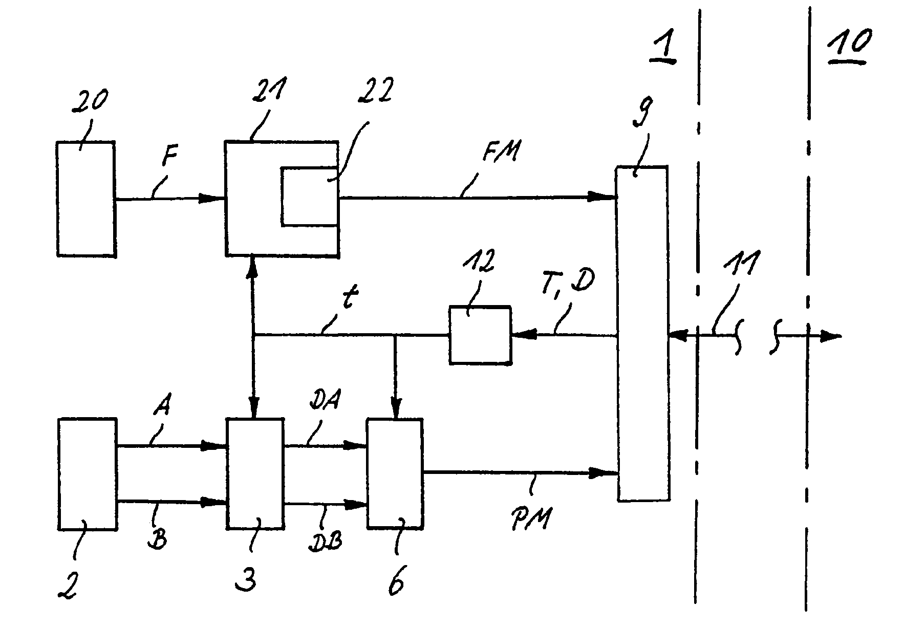
[0031]The position measuring device 1 represented in FIG. 1 includes a detector unit 2, to whose output several analog scanning signals A, B, which are phase-shifted by 90° with respect to each other, have been applied. Such a detector unit 2 is known per se, wherein the scanning signals A, B are generated by opto-electrical, magnetic, inductive or capacitive scanning of an incremental graduation, or are derived from an interferometer. As a rule, the scanning signals A, B are sinusoidal.

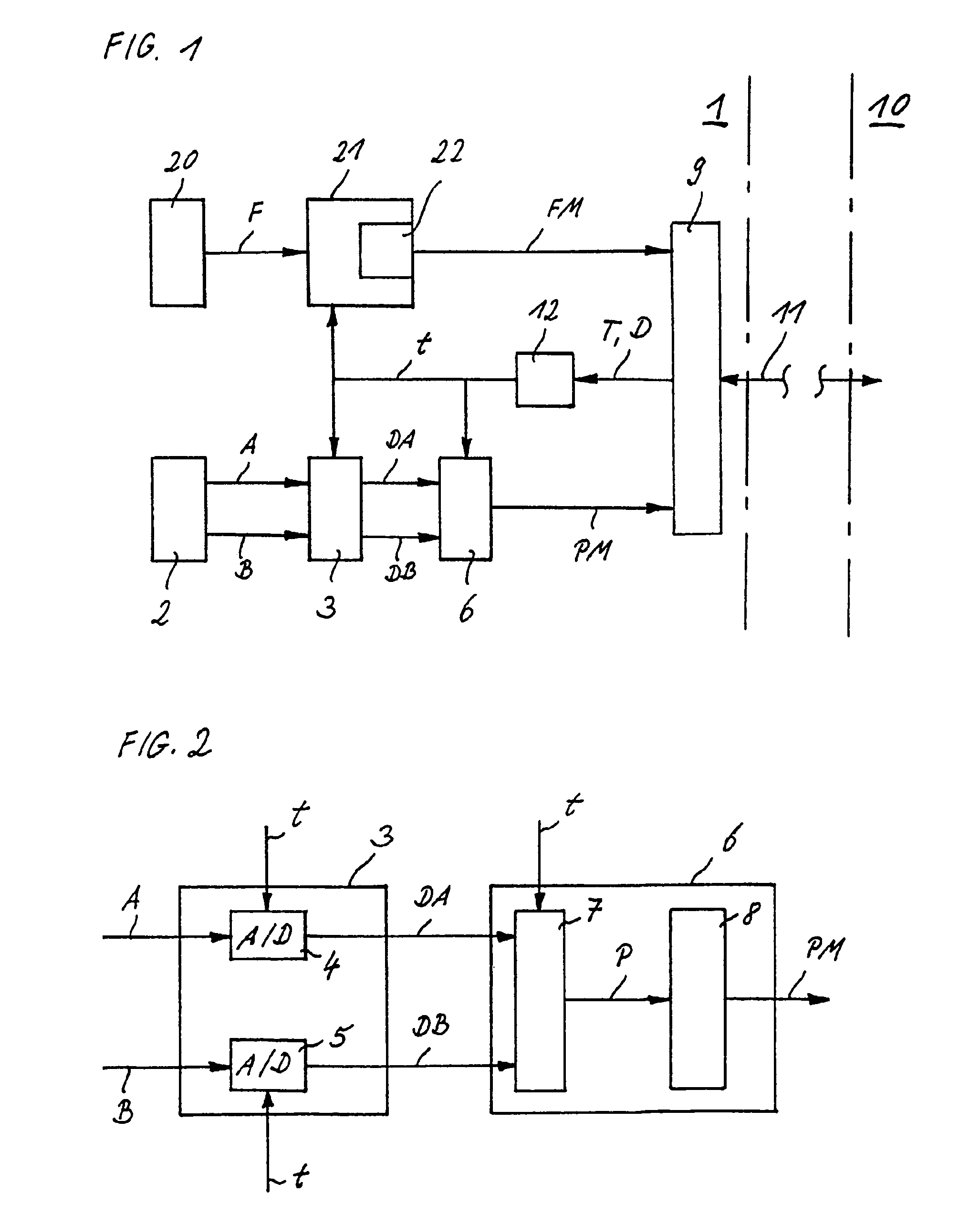
[0032]The scanning signals A, B are supplied to a transmitting unit 3, which takes on (samples) the instantaneous values of the scanning signals A, B synchronously at a predetermined scanning clock pulse t and digitizes them. As represented in FIG. 2, take-over and digitizing are realized by A / D converters 4 and 5.

[0033]The synchronously transmitted value pairs of the digitized scanning signals DA, DB are supplied to a processing unit 6, in which a resulting position measuring value PM is established...


PUM


Abstract

A position measuring device including a detector unit that generates position-dependent scanning signals and a transmitting unit that transmits instantaneous values of the position-dependent scanning signals in a preset scanning clock pulse. A processing unit that establishes a resulting measured position value by filtering instantaneous values of several scanning clock pulses and an interface which, on the basis of a transmission clock pulse transmits the resulting measured position value to a sequential electronic unit via a serial data line.

Description

[0001]Applicant claims, under 35 U.S.C. §§ 120 and 365, the benefit of priority of the filing date of Oct. 1, 2002 of a Patent Cooperation Treaty patent application, copy attached, Serial Number PCT / EP02 / 10974, filed on the aforementioned date, the entire contents of which are incorporated herein by reference, wherein Patent Cooperation Treaty patent application Serial Number PCT / EP02 / 10974 was not published under PCT Article 21(2) in English.[0002]Applicant claims, under 35 U.S.C. § 119, the benefit of priority of the filing date of Oct. 4, 2001 of a German patent application, copy attached, Serial Number 101 49 174.3, filed on the aforementioned date, the entire contents of which are incorporated herein by reference.BACKGROUND OF THE INVENTION[0003]1. Field of the Invention[0004]The present invention relates to a method for position determination in a position measuring device, as well as to a position measuring device for executing the method.[0005]2. Description of the Related A...

Claims


Application Information

Patent Timeline
Patent Type & Authority Patents(United States)
IPC IPC(8): G01C17/00G01D5/244
CPCG01D5/24476
Inventor HAGL, RAINER
Owner DR JOHANNES HEIDENHAIN GMBH
Why Eureka
Try Eureka