
Synchronization of distributed simulation nodes by keeping timestep schedulers in lockstep

a distributed simulation and lockstep technology, applied in the direction of pulse amplitude modulation, cad circuit design, instruments, etc., can solve the problem that single-system simulation has become less desirabl

Inactive Publication Date: 2006-03-28
ORACLE INT CORP
View PDF35 Cites 35 Cited by
  • Summary
  • Abstract
  • Description
  • Claims
  • Application Information

AI Technical Summary

Benefits of technology

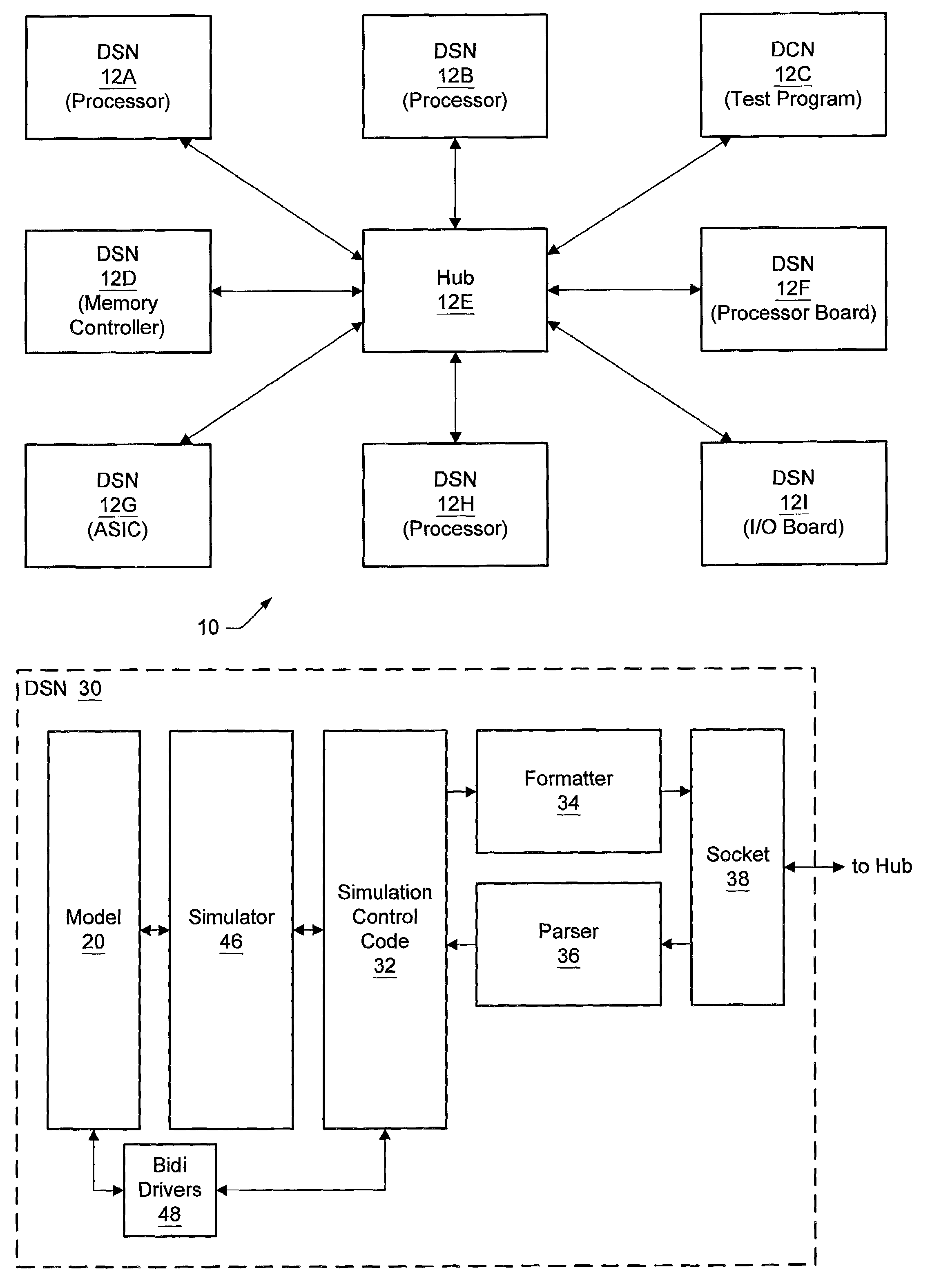
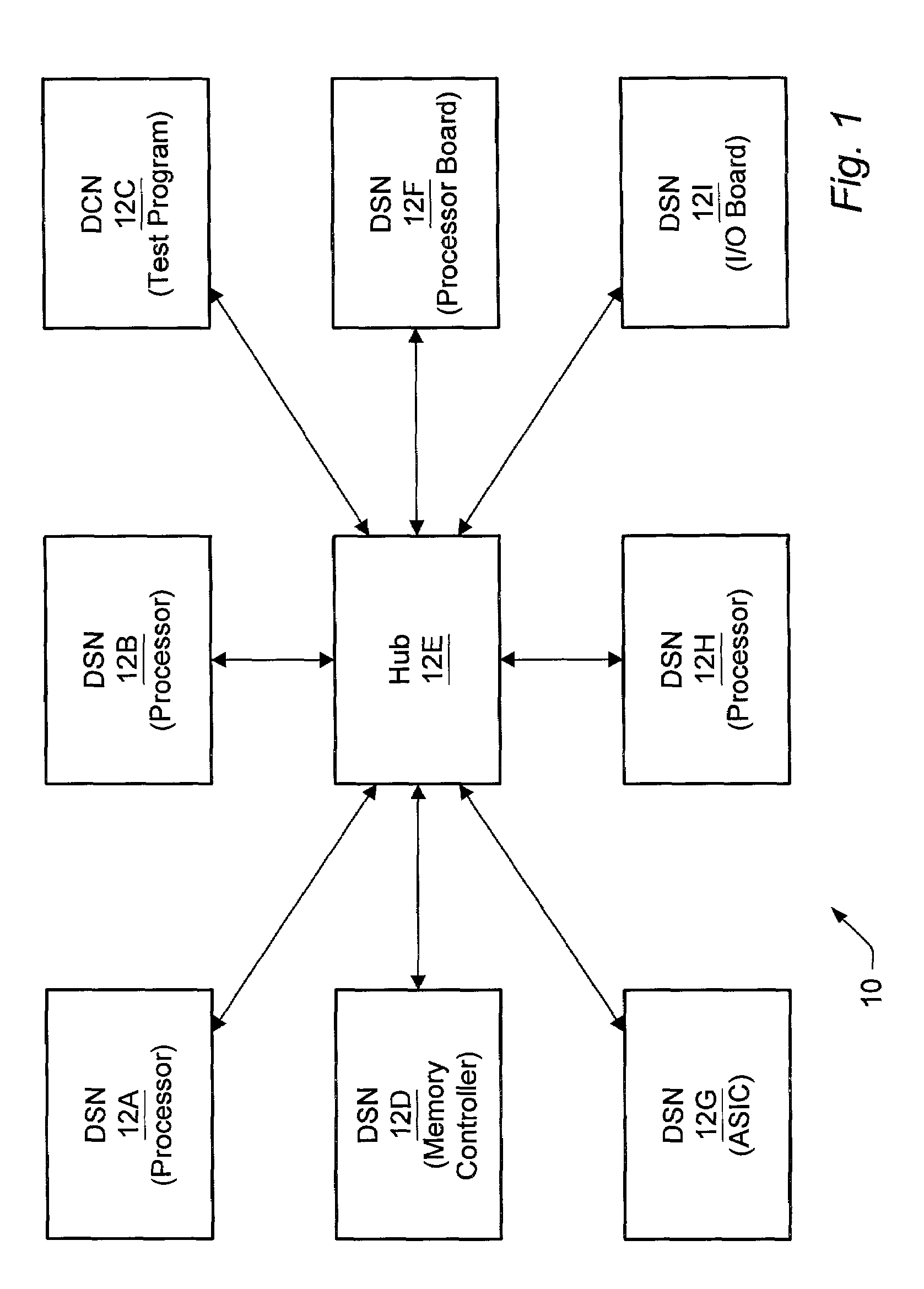
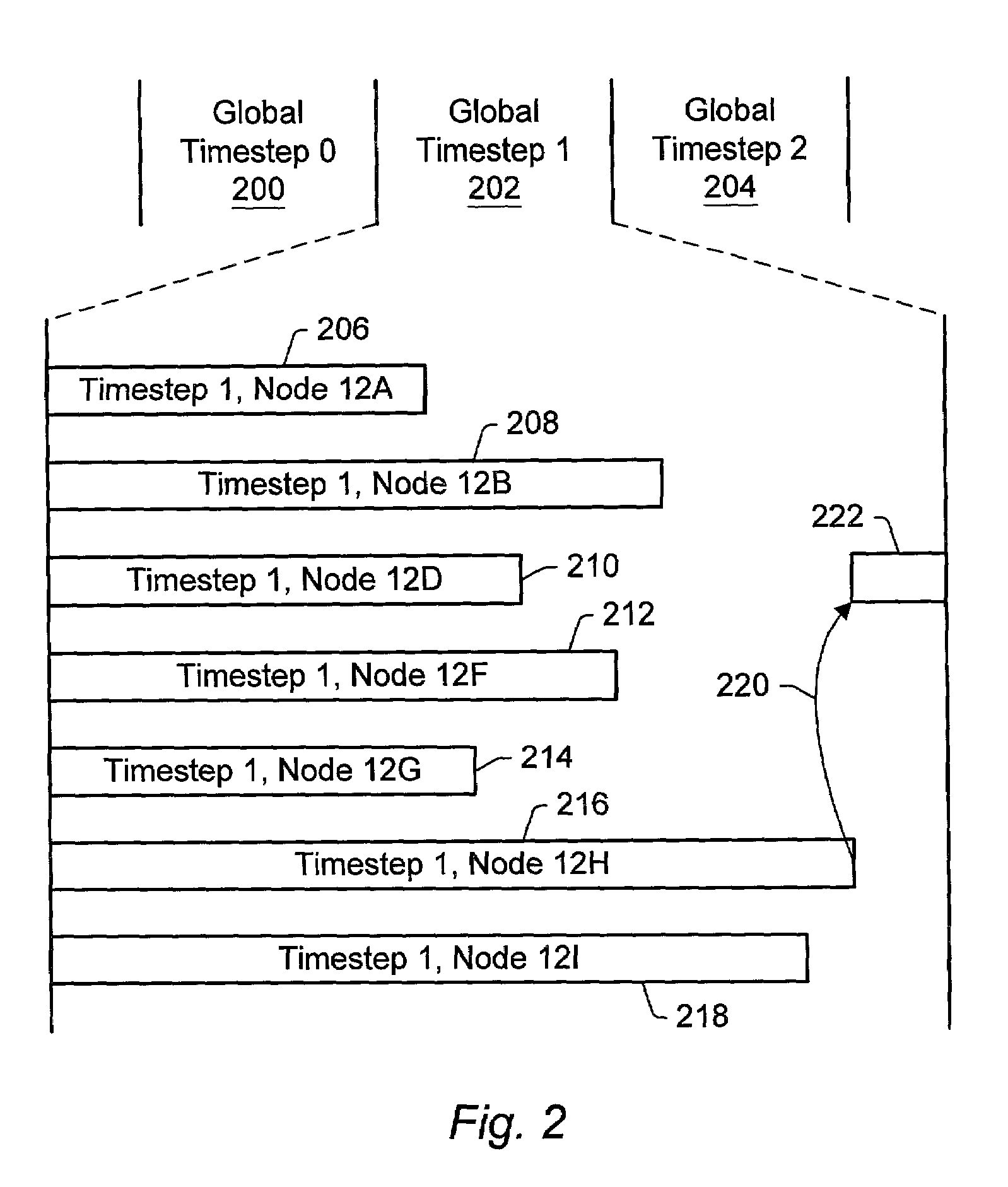
"The patent describes a system for simulating a complex system using multiple computers. These computers work together to create a synchronized simulation, where each computer takes a turn to simulate a portion of the system. This is done by a central computer that sends instructions to each computer and receives confirmation that the previous step is complete. This system allows for more complex and realistic simulations to be performed."

Problems solved by technology

However, as the electronic systems (and the components forming systems) have grown larger and more complex, single-system simulation has become less desirable.

Method used


Image

  • Synchronization of distributed simulation nodes by keeping timestep schedulers in lockstep
  • Synchronization of distributed simulation nodes by keeping timestep schedulers in lockstep
  • Synchronization of distributed simulation nodes by keeping timestep schedulers in lockstep

Examples


second embodiment

A Zero-Time and Real-Time Phases of a Timestep

[0075]Turning next to FIGS. 8–13, a second embodiment of the distributed simulation system 10 in which a timestep includes at least two phases is shown. Each of the phases may be synchronized among the nodes in a manner similar to the above description. Additionally, exiting one of the phases (the last within the timestep) also results in exiting the timestep. Accordingly, the synchronization of timestep transitions may coincide with the synchronizing of one of the phase transitions.

[0076]In the embodiment described below, the NOP command is used by the DSNs to indicate that no communication is desired by the node. Accordingly, the NOP command may be an example of the local timestep complete command for the embodiment below. Similarly, the NOP command may be used as the “phase complete” command for phase synchronization. Two commands are defined to control the transition out of a phase (real time done, or RT_Done, and zero time done, or...


PUM


Abstract

A distributed simulation system includes a plurality of nodes. Each node is configured to simulate a portion of a system under test. The simulation is performed as a series of timesteps. The transition between timesteps is synchronized in the plurality of nodes. In one implementation, the distributed simulation system includes a hub which is configured to synchronize the transition between timesteps in the plurality of nodes. For example, in one embodiment, the hub may receive commands from each of the plurality of nodes. If each command indicates that the corresponding node is capable of completing the timestep, the hub transmits a command to each node indicating that the timestep is complete. The nodes may begin processing the next timestep in response to the command. In other embodiments, a hub may not be included.

Description

BACKGROUND OF THE INVENTION[0001]1. Field of the Invention[0002]This invention is related to the field of distributed simulation systems.[0003]2. Description of the Related Art[0004]Generally, the development of components for an electronic system such as a computer system includes simulation of models of the components. In the simulation, the specified functions of each component may be tested and, when incorrect operation (a bug) is detected, the model of the component may be changed to generate correct operation. Once simulation testing is complete, the model may be fabricated to produce the corresponding component. Since many of the bugs may have been detected in simulation, the component may be more likely to operate as specified and the number of revisions to hardware may be reduced. The models are frequently described in a hardware description language (HDL) such as Verilog, VHDL, etc. The HDL model may be simulated in a simulator designed for the HDL, and may also be synthes...

Claims


Application Information

Patent Timeline
Patent Type & Authority Patents(United States)
IPC IPC(8): G06F15/16G06F17/50H03K7/02
CPCG06F30/33
Inventor SIVIER, STEVEN A.FRANKEL, CARL B.CAVANAGH, CARLFREYENSEE, JAMES P.
Owner ORACLE INT CORP
Learn More