Pressing-out device for eccentric support joints

a technology of eccentric support joints and devices, which is applied in the direction of metal-working hand tools, metal-working equipment, metal-working hand tools, etc., can solve the problems that the support bell and/or the support surface of the bearing eye cannot be fully circumferentially supported by the support bell over the full circumferential, and the prior-art devices cannot be operatively positioned satisfactorily to the bearing bore or the surrounding bearing ey

Inactive Publication Date: 2006-04-04
KLANN SPEZIAL WERKZEUGBAU
View PDF10 Cites 5 Cited by
  • Summary
  • Abstract
  • Description
  • Claims
  • Application Information

AI Technical Summary

Benefits of technology

[0005]Consequently, the basic object of the present invention is to improve a device of the type such that the above-described drawbacks of the prior-art device are eliminated or at least mitigated.

Problems solved by technology

It was found that especially when they are used directly at the vehicle, the prior-art devices cannot be operatively positioned satisfactorily to the bearing bore or the bearing eye surrounding the bearing bore.
It may also happen in the case of such components with such a stop web that the support surface available for supporting the support bell at the bearing eye is not completely circumferentially extending, so that the support bell cannot be supported at the bearing eye over the full circumferential area.
The consequence of this is, in turn, that the support bell is tilted during the operative positioning or mounting and especially during the subsequent clamping operation and the support bell and / or the support surface of the bearing eye is thus damaged.
In addition, a defined pressing out of such a component is possible now only conditionally, because the supporting is no longer concentric with the component to be pressed out, and damage to the pressing may device may thus occur as well.

Method used


Image

  • Pressing-out device for eccentric support joints
  • Pressing-out device for eccentric support joints
  • Pressing-out device for eccentric support joints

Examples


Embodiment Construction

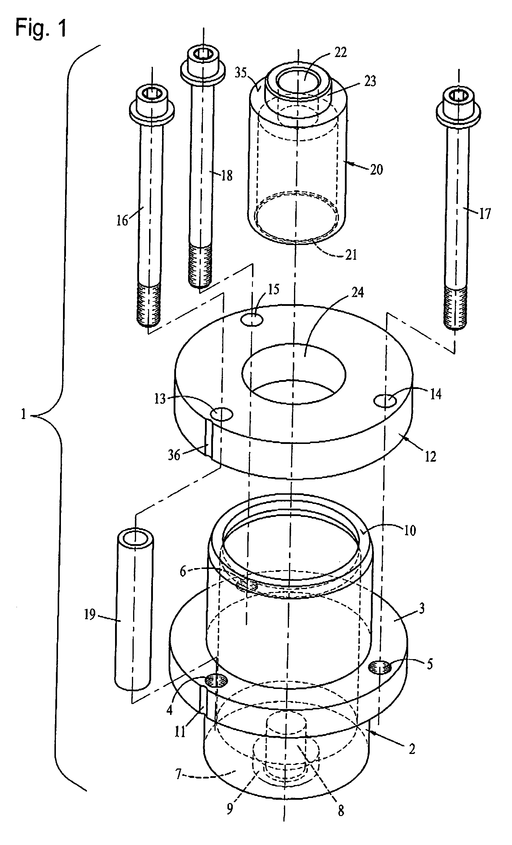
[0022]Referring to the drawings in particular, FIG. 1 shows a perspective exploded view of the components of a device 1 according to the present invention.

[0023]The device 1 according to the present invention comprises a support frame or support bell 2, which has a radially outwardly projecting holding web 3 on its outer circumference. This holding web 3 is provided with three internal threads 4, 5 and 6.

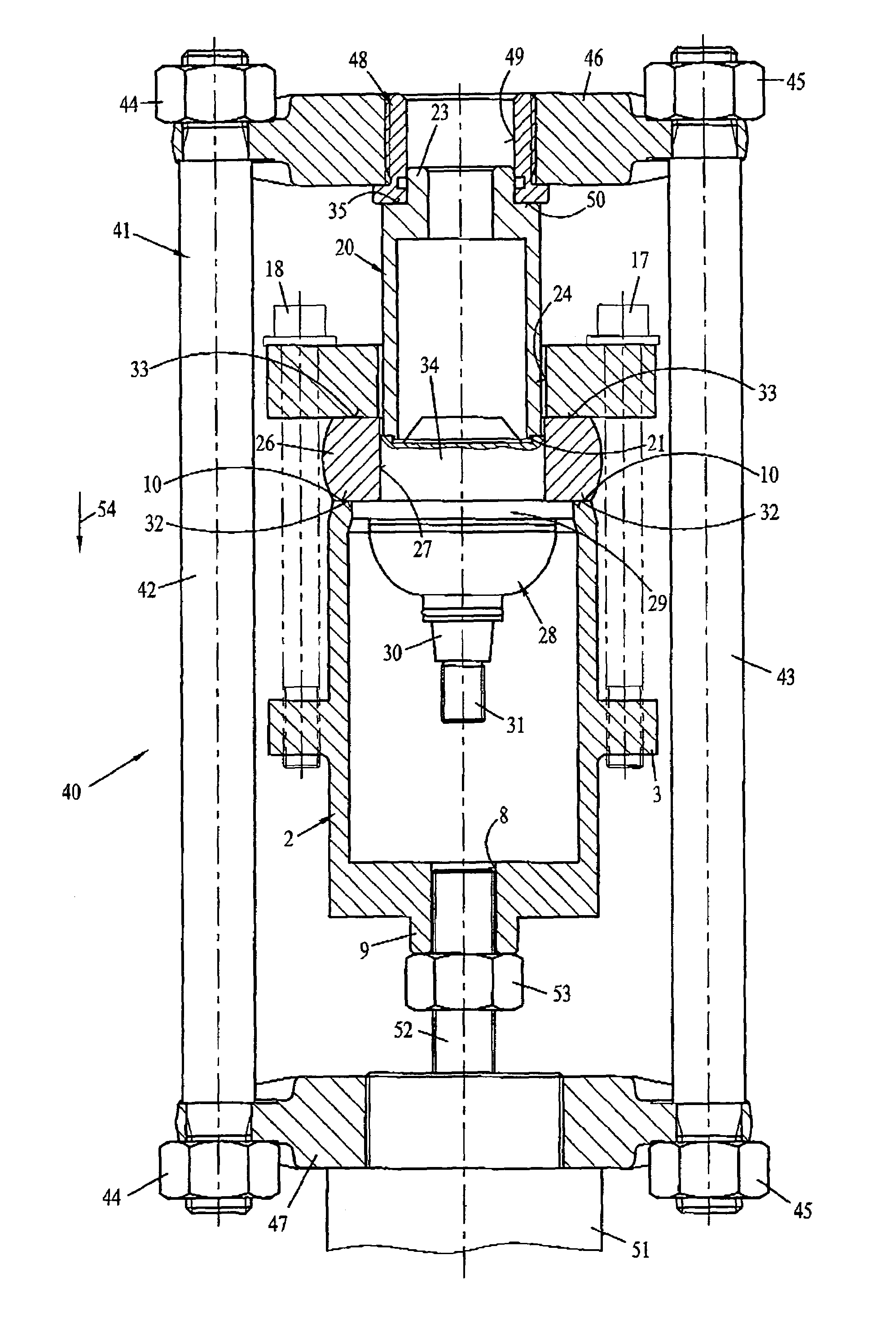
[0024]The support bell 2 has, furthermore, a front wall 7 with a central through hole 8 at its lower end. An axially downwardly projecting support cylinder 9, by means of which the support bell 2 can be coupled with a pressing device, is provided in the area of the said through hole 8. On its front side located opposite this support cylinder 9, the support bell 2 forms a front ring surface 10, via which the support bell 2 is supported at a corresponding support surface surrounding the bearing bore during the pressing of a component out of the said bearing bore, as will be described ...


PUM

PropertyMeasurementUnit
areaaaaaaaaaaa
pressureaaaaaaaaaa
distanceaaaaaaaaaa

Abstract

A device (1) is provided for pressing out a component pressed into a bearing bore of a bearing eye of an axle component. The device includes a support bell (2) being supported at the bearing eye in the area around the bearing bore and a pressure piece (20), which can be pushed axially through the bearing bore together with the component. The pressing device can be operatively positioned or mounted to the support bell (2) and to the pressure piece (20) for the pressing-out operation. To make it possible to carry out the pressing-out operation simply and reliably, provisions are made for arranging a clamping plate (12), which can be detachably connected to the support bell (2) and via which the support bell (2) is held at the bearing eye (24) in a firmly seated manner, at the bearing eye (12) axially opposite the support bell (2).

Description

FIELD OF THE INVENTION[0001]The present invention pertains to a device for pressing out a component pressed into a bearing bore of a bearing eye of an axle component, comprising a support bell supported at the bearing eye in the area around the bearing bore and a pressure piece, which can be pushed together with the component axially through the bearing bore, wherein a pressing device can be mounted or operatively positioned relative to the support bell and the pressure piece for the pressing-out operation.BACKGROUND OF THE INVENTION[0002]Devices of the type are known from, e.g., DE 37 30 017 C1, DE 42 11 765 C2 or also DE 201 06 519.3 U1. The devices described in these documents are used essentially to press out wheel bearings pressed into a bearing bore of a motor vehicle axle or so-called silent bearings of an axle carrier of a motor vehicle. The feature common to them is that, on the one hand, a support bell or support frame is provided, which is supported in the circumferential...

Claims


Application Information

Patent Timeline
Patent Type & Authority Patents(United States)
IPC IPC(8): B23P19/04B25B27/06B25B27/073
CPCB25B27/062Y10T29/53861Y10T29/53878
Inventor KLANN, HORST
Owner KLANN SPEZIAL WERKZEUGBAU
Why Eureka
Try Eureka