Method and apparatus for manufacturing slip stopper

a manufacturing method and slip stopper technology, applied in the direction of load securing, transportation items, transportation and packaging, etc., can solve the problems of noise diffusing, increased production process and cost, and inevitable noise from the engine blowing upward from the cover, so as to achieve great slip stopper effect, easy manufacturing, and great slip stop effect

Inactive Publication Date: 2006-04-04
SHIN CATERPILLAR MITSUBISHI LTD CORP
View PDF25 Cites 5 Cited by
  • Summary
  • Abstract
  • Description
  • Claims
  • Application Information

AI Technical Summary

Benefits of technology

[0009]Thereby, a slip stopper which achieves a great slip stopping effect and can be used for a location where a problem occurs if a through hole is opened therein can be easily manufactured.
[0011]By using the first and second punching die units, a slip stopper which achieves a great slip stopping effect and can be used for a location where a problem occurs if a through hole is opened therein can be easily manufactured.
[0012]The invention can be widely applied in the technical fields of a method and an apparatus for manufacturing a slip stopper for various footings requiring a device to prevent slipping, such as the stepping surfaces of construction machines, floors, passageways, and stairs of building structures, floors and steps of buses, trucks, and special vehicles, decks of railroad vehicles and ships, scaffolding at construction sites, etc. The invention can also be used for a location where a problem occurs if a through hole is opened therein, and is useful in a case where it is necessary to readily manufacture a slip stopper having a great slip stopping effect at low cost.

Problems solved by technology

If the slip stopper having the through hole stamped out is used as it is as a cover to cover the upper surface of a construction machine, problems, such as rainwater or dirt entering the inside of the cover, heated air from an engine blowing upward from the cover, or noise diffusing, are inevitable.
However, the double structure increases production processes and costs in comparison with the single structure and, further, poses a problem in that mud or dust entering through the through hole of the slip stopper accumulates between the slip stopper and the lower side flat steel plate or in the through hole, and makes cleaning difficult.

Method used


Image

  • Method and apparatus for manufacturing slip stopper
  • Method and apparatus for manufacturing slip stopper
  • Method and apparatus for manufacturing slip stopper

Examples


Embodiment Construction

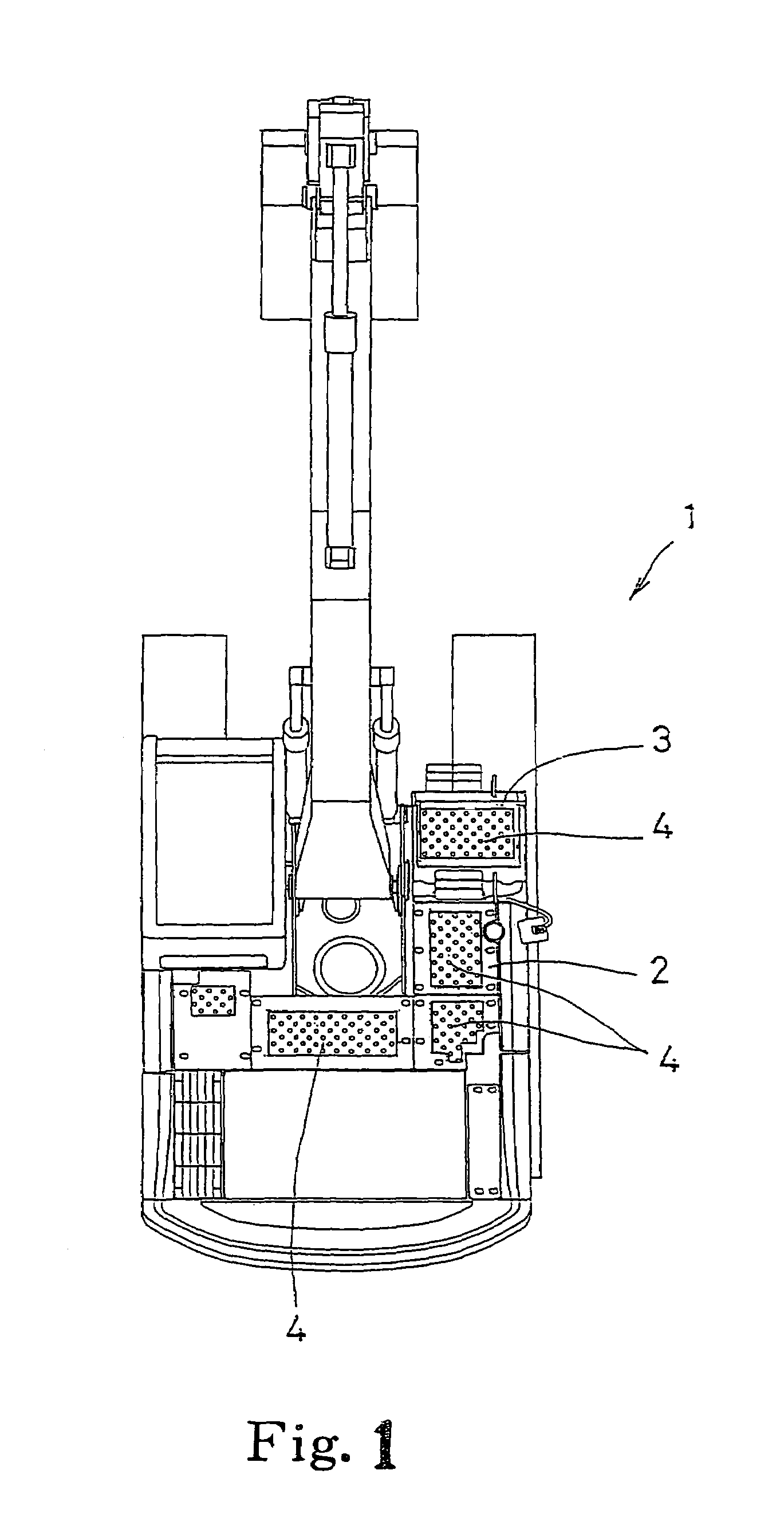
[0025]In the drawings, a construction machine (hydraulic excavator) 1 is constructed so that the upper surfaces of a cover 2 covering the upper surface of the construction machine body and a tool box 3 are formed as stepping surfaces on which a worker walks and steps during maintenance, and a slip stopper 4 to which the invention has been applied is used on these stepping surfaces.

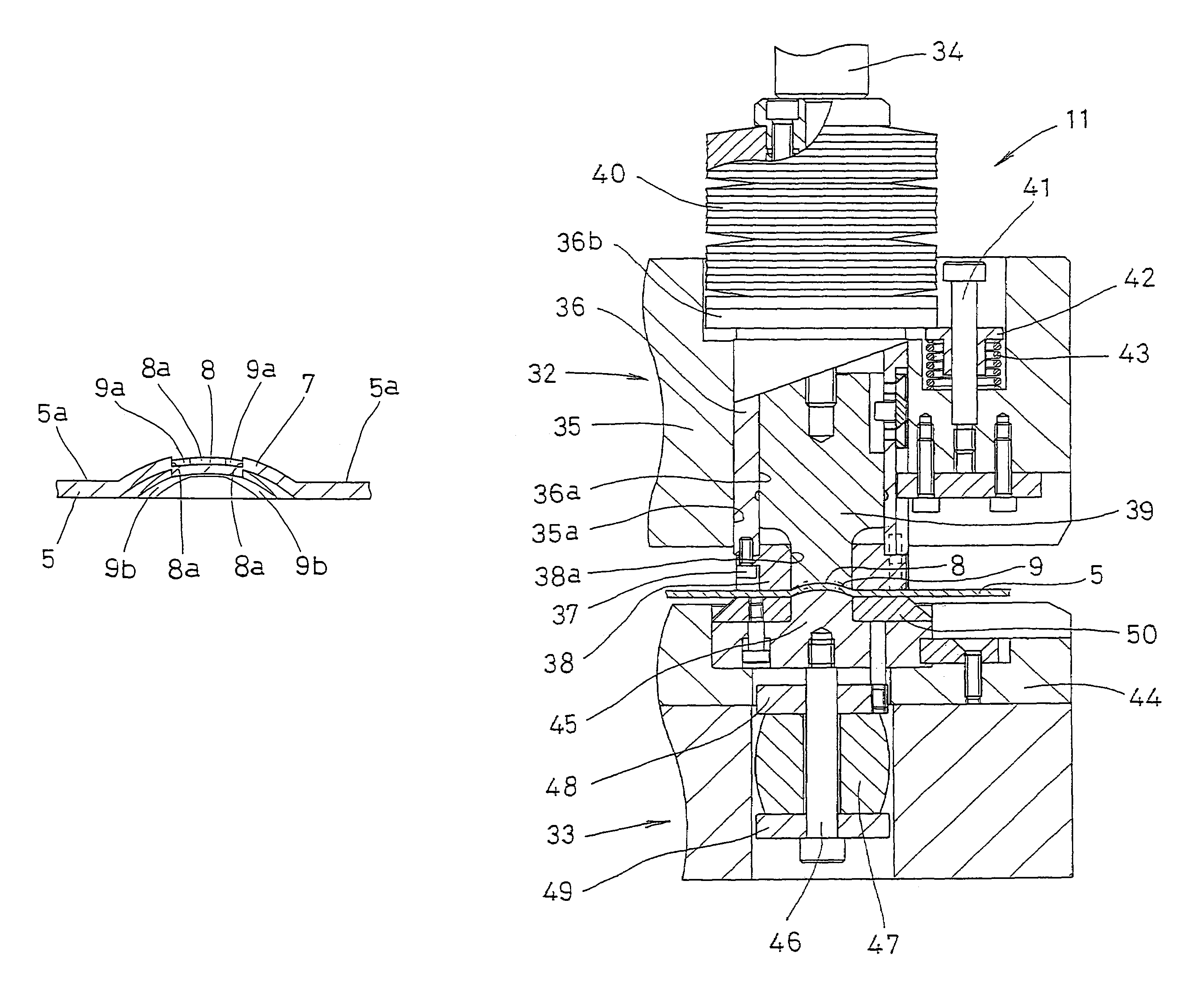
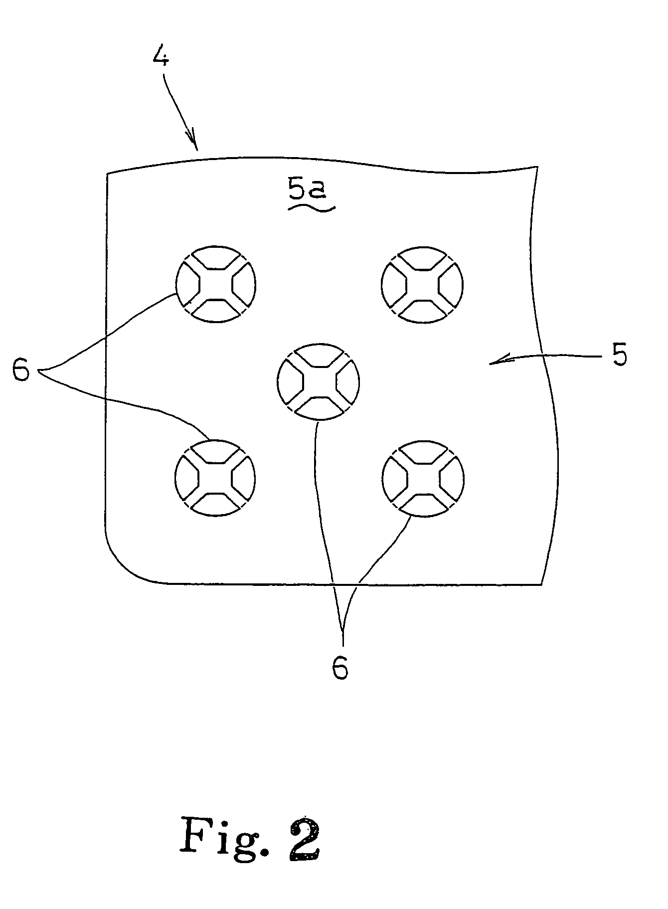
[0026]The slip stopper 4 (FIGS. 2–3(C)) has a plurality of slip stopping parts 6 formed in a vertically and horizontally running pattern on a flat steel plate 5. In the slip stopping parts 6, a concave portion 8 and drain channels 9 are formed in a protruding portion 7, that protrudes in the plate thickness direction from the upper surface 5a of the steel plate 5, by shear planes 8a, 9a described later.

[0027]Namely, the protruding portion 7 is circular in a plan view and has a roughly arc-shaped section. A roughly quadrilateral concave portion 8 is formed at the central portion of the upper surface side of...


PUM

PropertyMeasurementUnit
thicknessaaaaaaaaaa
heightaaaaaaaaaa
distanceaaaaaaaaaa

Abstract

An easy manufacturing method of a slip stopper, and apparatus therefor, that has a great slip stopping effect and can be used for a location where a problem occurs if a though hole is opened therein. After a protruding portion is formed on a steel plate, by using a first punching die unit, so as to protrude from the upper surface in a plate thickness direction, a concave portion and drain channels are formed in the protruding portion by shear planes that extend substantially perpendicular to the steel plate upper surface and have been half-blanked so as not to open a through hole in the steel plate by using a second punching die unit.

Description

[0001]This application claims priority from JP2002-002651, filed Jan. 9, 2002 through PCT / JP02 / 11741 filed Nov. 11, 2002. The disclosures of the identified documents are enclosed herein by reference thereto.BACKGROUND OF THE INVENTION[0002]1. Technical Field[0003]The invention relates to the technical fields of a method and an apparatus for manufacturing a slip stopper employed for a construction machine, such as a hydraulic excavator, or other surfaces that need to be non-slip.[0004]2. Background Art[0005]Generally, a slip stopper with a slip stopping function is occasionally used for floors, passageways, and stairs in building structures, floors and steps of buses, trucks and special vehicles, decks of railroad vehicles and ships, and scaffolding at construction sites. Such a slip stopper, for example, as shown in FIGS. 10(A)–10(C), has been conventionally known. This is a so-called striped steel plate that has a plurality of projections 51 molded in continuous patterned shape, an...

Claims


Application Information

Patent Timeline
Patent Type & Authority Patents(United States)
IPC IPC(8): B21D28/10E02F9/16B21D22/04B21D35/00B60P7/08E02F9/24
CPCB21D22/04B60P7/0884B21D35/00
Inventor OHNO, SHUNJIIWASA, KAZUMICHINAKAJIMA, NORIOTSUJI, MASANORIDOI, TSUYOSHIKOUZU, YOSHIHISAMIYAKE, HIDEYUKISUGIMOTO, MAMORU
Owner SHIN CATERPILLAR MITSUBISHI LTD CORP
Why Eureka
Try Eureka