Molten metal feed apparatus of die casting machine, molten metal feed method, and ladle
- Summary
- Abstract
- Description
- Claims
- Application Information
AI Technical Summary
Benefits of technology
Problems solved by technology
Method used
Image

Examples
first embodiment
[0027
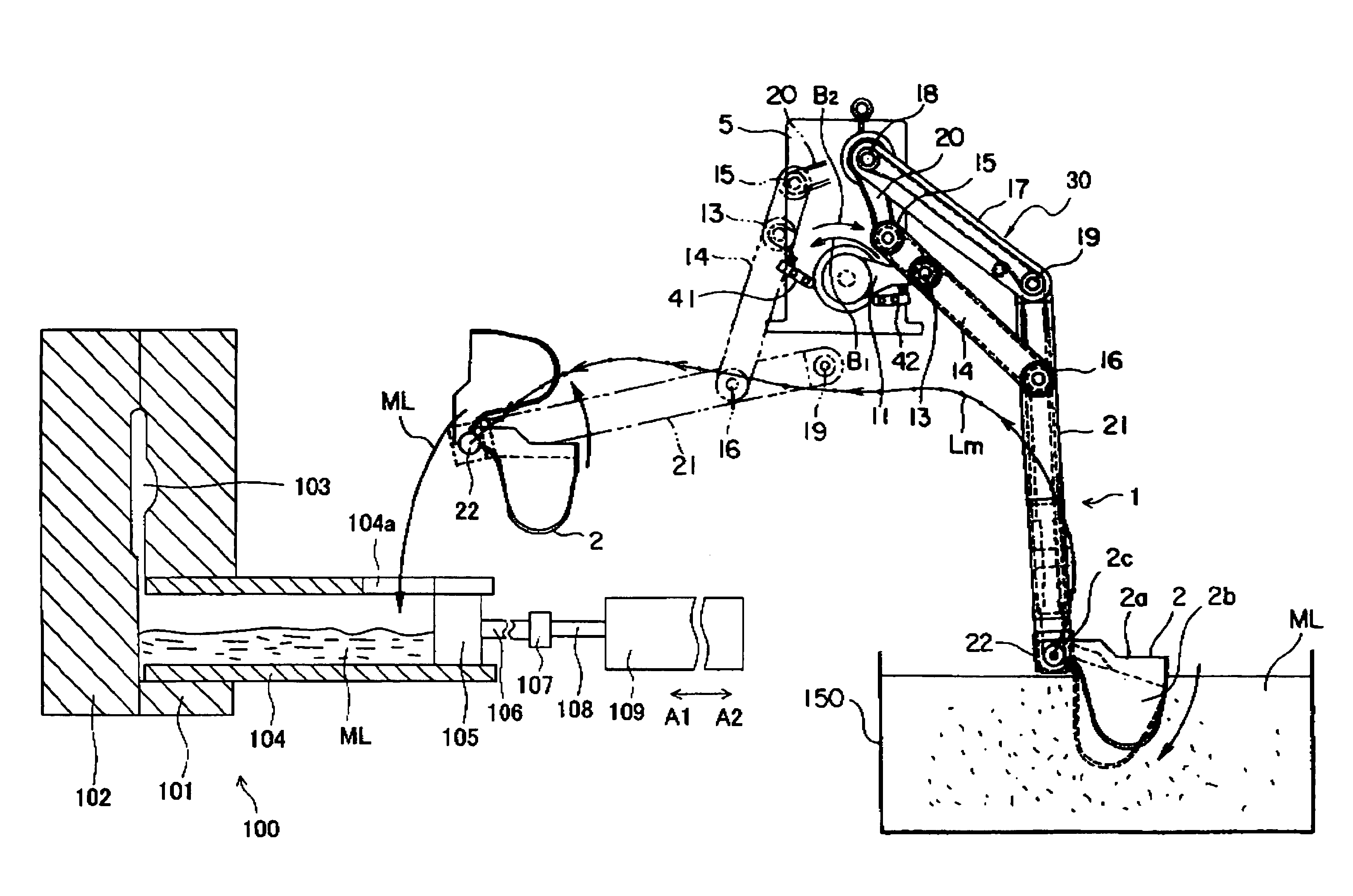
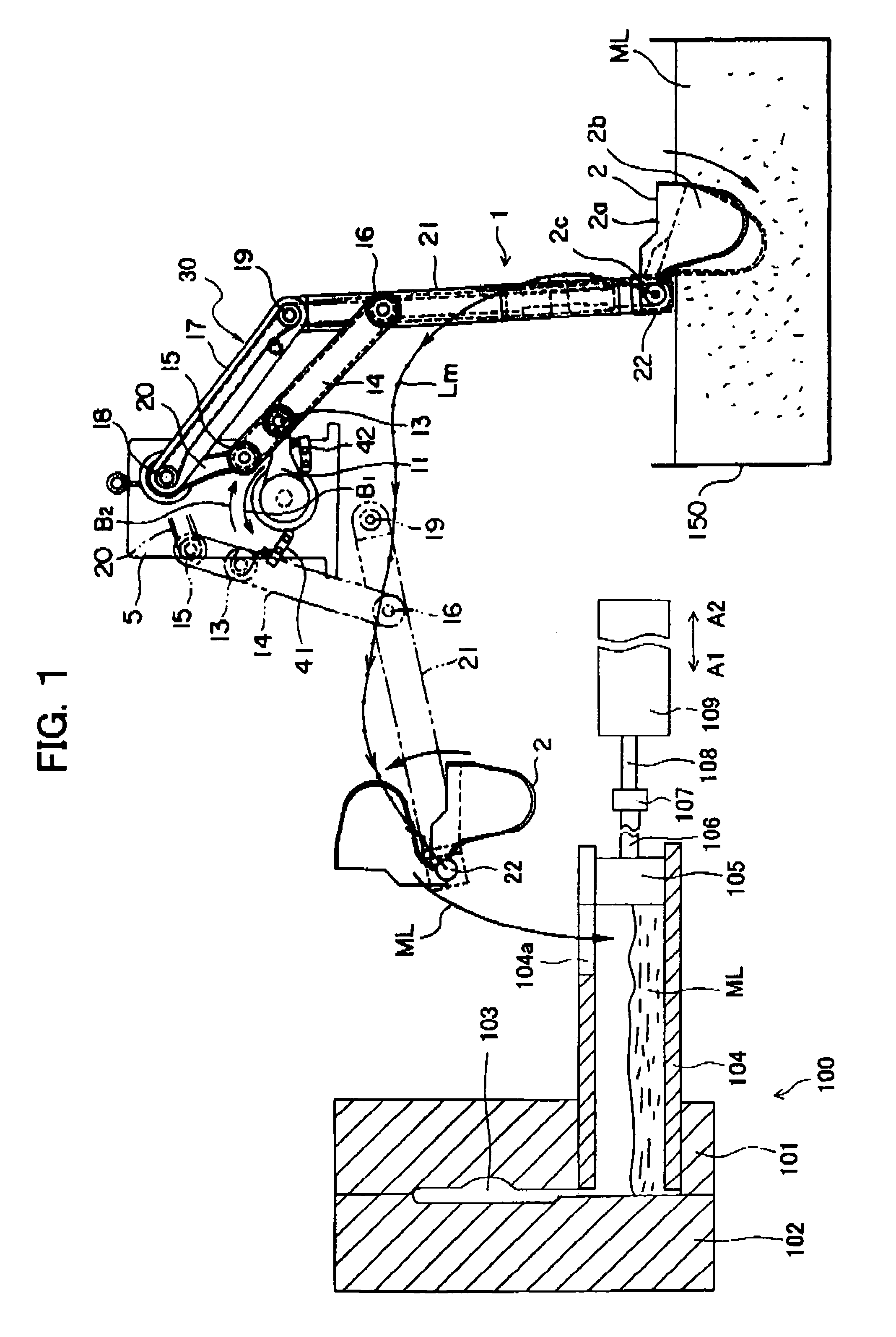
[0028]FIG. 1 is a view of the configuration of a molten metal feed apparatus and a die casting machine according to an embodiment of the present invention. In FIG. 1, a die casting machine 100 is comprised of a fixed die 101, a movable die 102, a sleeve 104, a plunger 105, an injection cylinder 109, etc.
[0029]The fixed die 101 is held by a not shown fixed die plate of a die clamping system, while the movable die 102 is held by a not shown movable die plate of the die clamping system. The fixed die 101 and the movable die 102 are opened, closed, and clamped by the not shown die clamping system. The fixed die 101 and movable die 102 form a cavity 103 between them. This cavity 103 is communicated with the sleeve 104.
[0030]The sleeve 104 is for example a cylindrical member formed by a metal or other material. One end is positioned at the fixed die 101, while the other end is provided with an opening 104a for feeding molten metal. The plunger 105 is coupled to a front end of a plung...
second embodiment
[0048
[0049]Next, a molten metal feed apparatus according to another embodiment of the present invention will be explained. The molten metal feed apparatus according to the present embodiment has a conveyor system and a ladle similar in basic structures of these with the first embodiment. Different components will be explained.
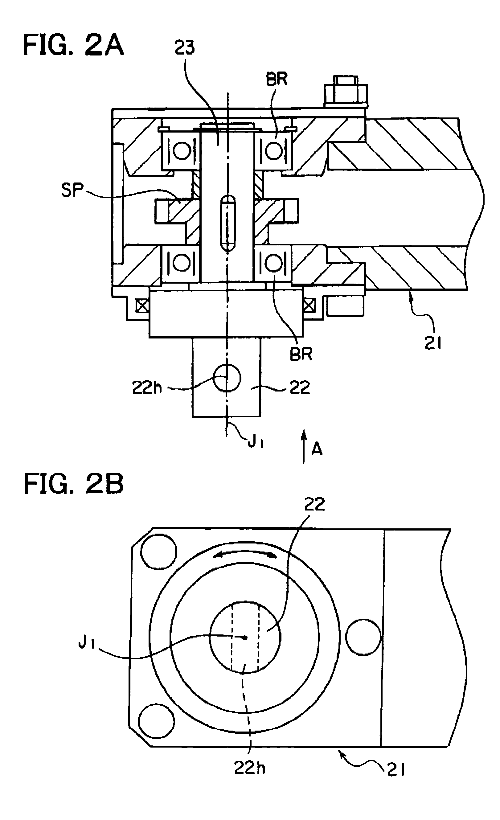
[0050]FIG. 7A is a cross-sectional view of the structure of the front end of the fifth arm 21A of the conveyor system according to the present embodiment taken along the longitudinal direction of the fifth arm 21A, while FIG. 7B is a side view seen from the direction of the arrow A of FIG. 7A. As shown in FIGS. 7A and 7B, one end of the rotary shaft 23 is formed with a flange 25. This flange 25 is formed with a mounting shaft 22. The mounting shaft 22 is formed with a pin hole 3k in its diametrical direction. As shown in FIGS. 7A and 7B, the axial line J1 of the rotary shaft 23 and the axial line J3 of the mounting shaft 22 are apart by exactly the distance Lb....
third embodiment
[0054
[0055]Next, a molten metal feed apparatus according to still another embodiment of the present invention will be explained. In the first embodiment explained above, the positional relationship between the rotary shaft 23 and the ladle 2 was fixed. In the present embodiment, as shown in FIG. 10, a connection plate 25 is interposed between the rotary shaft 23 (mounting shaft 22) and ladle 2 and the connection plate 25 is provided with a plurality of mounting holes 25ha to 25hd, whereby the positional relationship between the front end 2e of the pouring spout of the ladle 2 and the axial line J1 of the rotary shaft 23 can be changed.
[0056]Specifically, the connection plate 25 is formed with mounting holes 25ha to 25hd enabling insertion of the rotary shaft 22 at four different locations concentrically about the front end 2e of the pouring spout 2d of the ladle 2. By periodic rotation among the rotary shaft 23 (mounting shaft 22) and connection holes 25ha to 25hd, the range of move...
PUM
 Abstract
Description
Claims
Application Information
 - R&D
- Intellectual Property
- Life Sciences
- Materials
- Tech Scout
- Unparalleled Data Quality
- Higher Quality Content
- 60% Fewer Hallucinations
Browse by: Latest US Patents, China's latest patents, Technical Efficacy Thesaurus, Application Domain, Technology Topic, Popular Technical Reports.
© 2025 PatSnap. All rights reserved.Legal|Privacy policy|Modern Slavery Act Transparency Statement|Sitemap|About US| Contact US: help@patsnap.com