
Auto cycled pipeline system

a pipeline system and auto cycle technology, applied in the direction of machines/engines, process and machine control, instruments, etc., can solve the problems of reducing the yield rate of process but also the damage of machines, the inability to control the purity of fluid in the supply pipeline system, and the inability to easily pollute ultra pure water, etc., to achieve excellent yield rate, high fluid purity, and no manpower or energy consumption

Inactive Publication Date: 2005-06-30
UNITED MICROELECTRONICS CORP
View PDF1 Cites 5 Cited by
  • Summary
  • Abstract
  • Description
  • Claims
  • Application Information

AI Technical Summary

Benefits of technology

[0007] One objective of the present invention is to prevent the stagnant fluid area with deteriorated water from forming in the auxiliary main pipe by the auto cycled pipeline system, to keep high purity of fluid in the supply pipeline system and an excellent yield rate in the process.
[0008] The other objective of the present invention is to prevent the area with stagnant fluid and deteriorated water from forming in the auxiliary main pipe, it is not necessary to clean the auxiliary main pipe before working and can be used immediately.
[0009] The other objective of the present invention is to keep the fluid in auxiliary main pipe cycling and flowing by the auto cycled pipeline system and without any manpower or energy consumption.
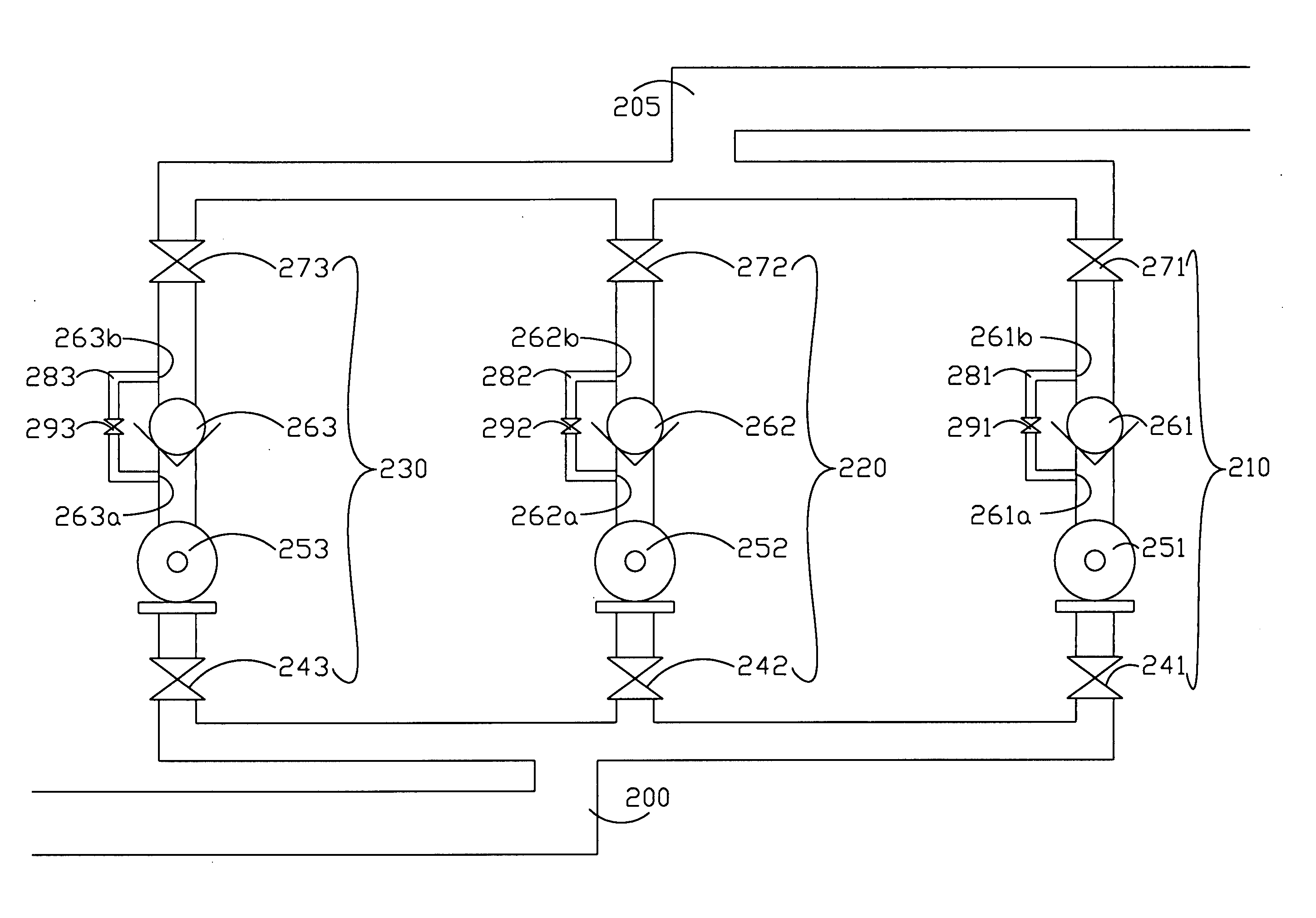
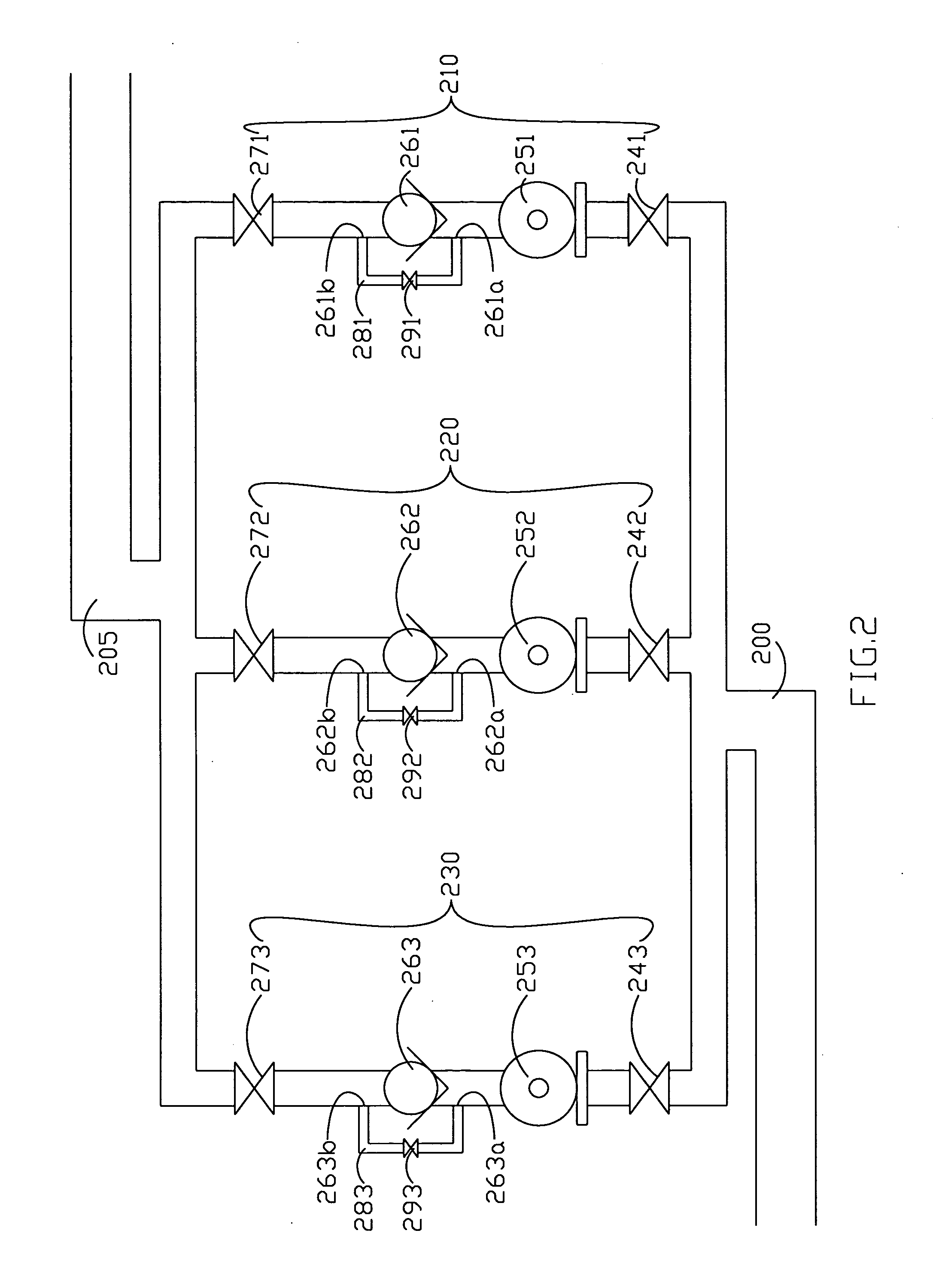
[0010] The present invention provides an auto cycled pipeline system including a plurality of main pipes, a plurality of cycle pipes, and a plurality of control values. The plurality of main pipes arranged in parallel and used to pump the fluid, and one side of each main pipe is connected to an inlet pipe, the other side of each main pipe is connected to an exit pipe. Each main pipe has a check value and a cycle pipe. One side of each cycle pipe is attached to a foregoing joint in front of the check value and the other side is attached to a rearward joint behind the check value of each main pipe. And each cycle pipe has a control value. The stagnant fluid in the stopped main pipe can be cycled by the cycle pipe of the pipeline system automatically, to prevent deterioration and to keep the purity of the fluid in the pipeline system.

Problems solved by technology

When the purity of high-grade gas or pure water become unstable, not only the yield rate of process is reduced but also the machine be damaged.
Therefore, how to control the purity of fluid in the supply pipeline system becomes an important issue.
If an area of stagnant fluid is formed in the auxiliary main pipe, the ultra pure water will be easily polluted and it will be difficult to clean the deteriorated water out.

Method used


Image

  • Auto cycled pipeline system
  • Auto cycled pipeline system
  • Auto cycled pipeline system

Examples


Embodiment Construction

[0014] Some embodiments of the invention will be described exquisitely below. Besides, the invention can also be practiced extensively in other embodiments. That is to say, the scope of the invention should not be restricted by the proposed embodiments. The scope of the invention should be based on the claims proposed later. Then, the components of the supply pipeline system are not shown to scale. Some dimensions are exaggerated to the related components to provide a more clear description and comprehension of the present invention.

[0015]FIG. 2 shows that apply the auto cycled pipeline system to ultra pure water supply pipeline system. Referring to FIG. 2, main pipe A 210, main pipe B 220 and auxiliary main pipe 230 are arranged in parallel, one side of each main pipe connecting to an inlet pipe 200 and the other side of each main pipe connecting to an exit pipe 205. Generally speaking, the farther side of the inlet pipe 200 connecting to an ultra pure water tank or any supply sou...


PUM


Abstract

An auto cycled pipeline system includes a plurality of main pipes, a plurality of cycle pipes, and a plurality of control values. The plurality of main pipes arranged in parallel and used to pump the fluid, and one side of each main pipe is connected to an inlet pipe, the other side of each main pipe is connected to an exit pipe. Each main pipe has a check value and a cycle pipe. One side of each cycle pipe is attached to a foregoing joint in front of the check value and the other side is attached to a rearward joint behind the check value of each main pipe. And each cycle pipe has a control value. The stagnant fluid in the stopped main pipe can be cycled by the cycle pipe of the pipeline system automatically, to prevent deterioration and to keep the purity of the fluid in the pipeline system.

Description

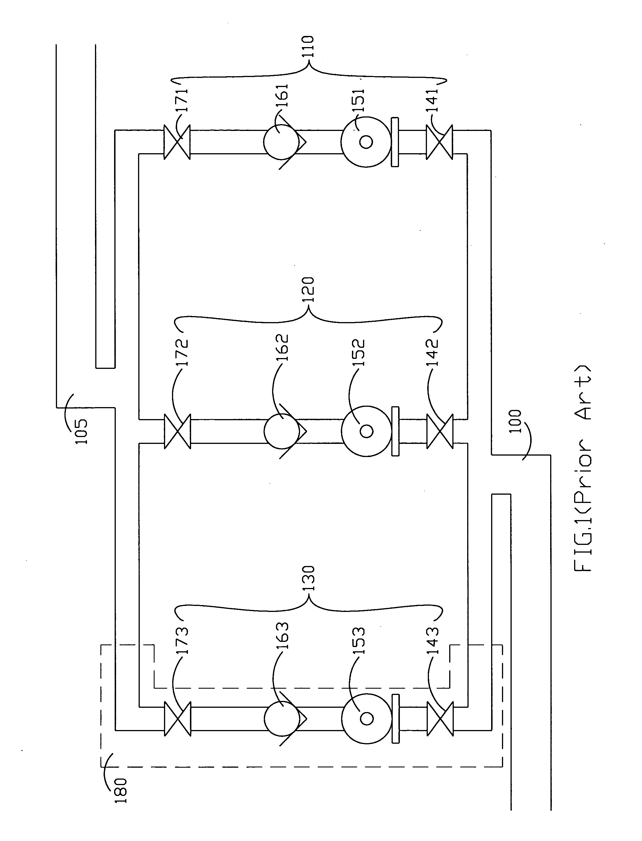
BACKGROUND OF THE INVENTION [0001] 1. Field of the Invention [0002] The present invention relates to a fluid supply system and more particularly to an auto cycled pipeline system that keeps the fluid clean by preventing stagnant fluid in pipes. [0003] 2. Description of the Prior Art [0004] In semiconductor manufacture, a large amount of high-grade gas or pure water is used in various processes such as chemical vapor deposition, dry etching, sputtering and cleaning. When the purity of high-grade gas or pure water become unstable, not only the yield rate of process is reduced but also the machine be damaged. Therefore, how to control the purity of fluid in the supply pipeline system becomes an important issue. [0005]FIG. 1 shows a typical supply pipeline system for ultra pure water supply. Referring to FIG. 1, main pipe A 110, main pipe B 120 and auxiliary main pipe 130 are arranged in parallel between an inlet pipe 100 and an exit pipeline 105. Each main pipe includes an inlet value ...

Claims


Application Information

Patent Timeline
IPC IPC(8): F17D1/08G05D7/00
CPCF17D1/08Y10T137/86163
Inventor CHEN, CHIEN-CHING
Owner UNITED MICROELECTRONICS CORP
Learn More