
Hermetic closed loop fluid system

a fluid system and closed loop technology, applied in the field of fluid circulating system, can solve the problems of high equipment failure potential, low efficiency, and low efficiency of fluid replacement, and achieve the effect of reducing the risk of equipment failure, and reducing the efficiency of fluid replacemen

Inactive Publication Date: 2006-04-04
VERTIV CORP
View PDF154 Cites 36 Cited by
  • Summary
  • Abstract
  • Description
  • Claims
  • Application Information

AI Technical Summary

Problems solved by technology

However, the material and structural characteristics of these mechanical components cause a slow loss of fluid from the fluid system over a period of time.
In microprocessor cooling systems, replacing fluid which has been lost would be very burdensome and expensive due to the difficulty of dismantling the cooling system and replacing the small scale components.
In addition, refilling of fluid in a microprocessor cooling system would cause great potential for equipment failures, safety risks, and loss of data owing to a short circuit caused by spilled fluid.
The permeability and diffusion rates of single phase and two phase fluid through these components into the surrounding environment are unacceptably high due to the materials of which these components are made.
The high permeability and diffusion rates of these materials make it almost impossible to prevent escape of the fluid from the cooling system.
Therefore, the cooling system is not able to maintain its integrity over the expected life of the system and eventually dry up as well as create humidity within the computer chassis.

Method used


Image

  • Hermetic closed loop fluid system
  • Hermetic closed loop fluid system
  • Hermetic closed loop fluid system

Examples


Embodiment Construction

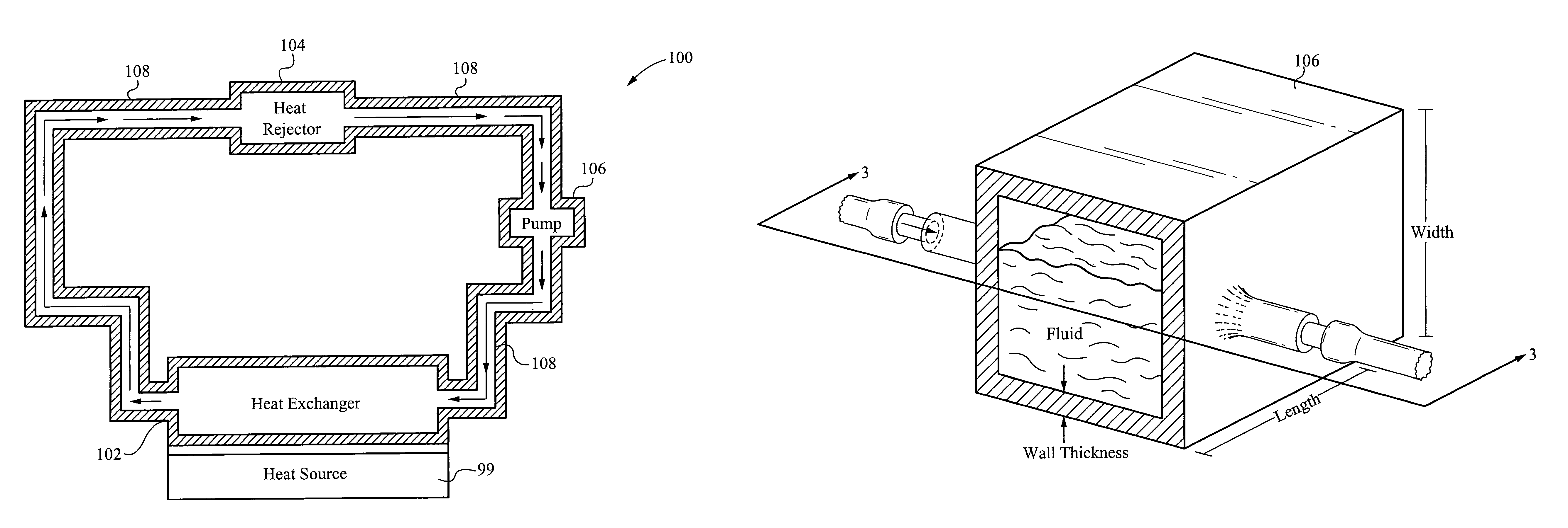
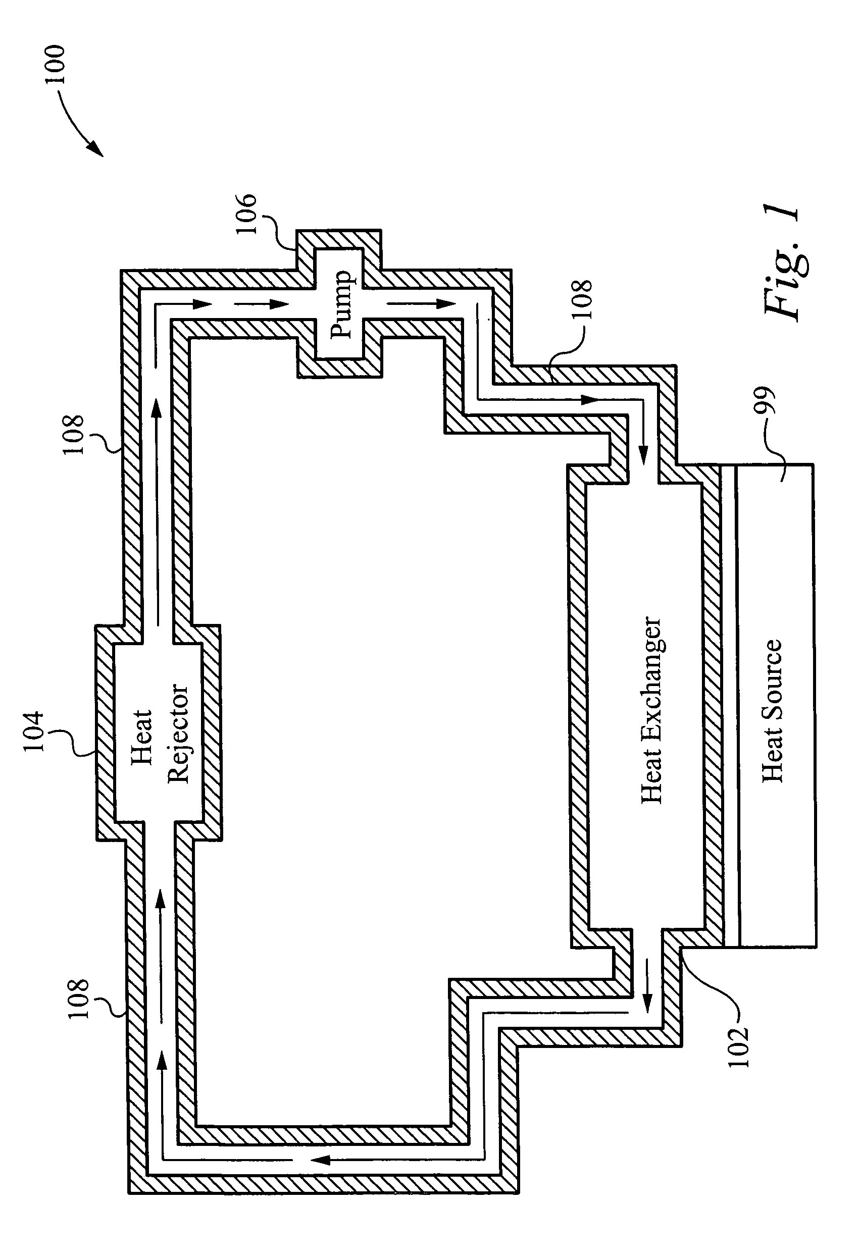
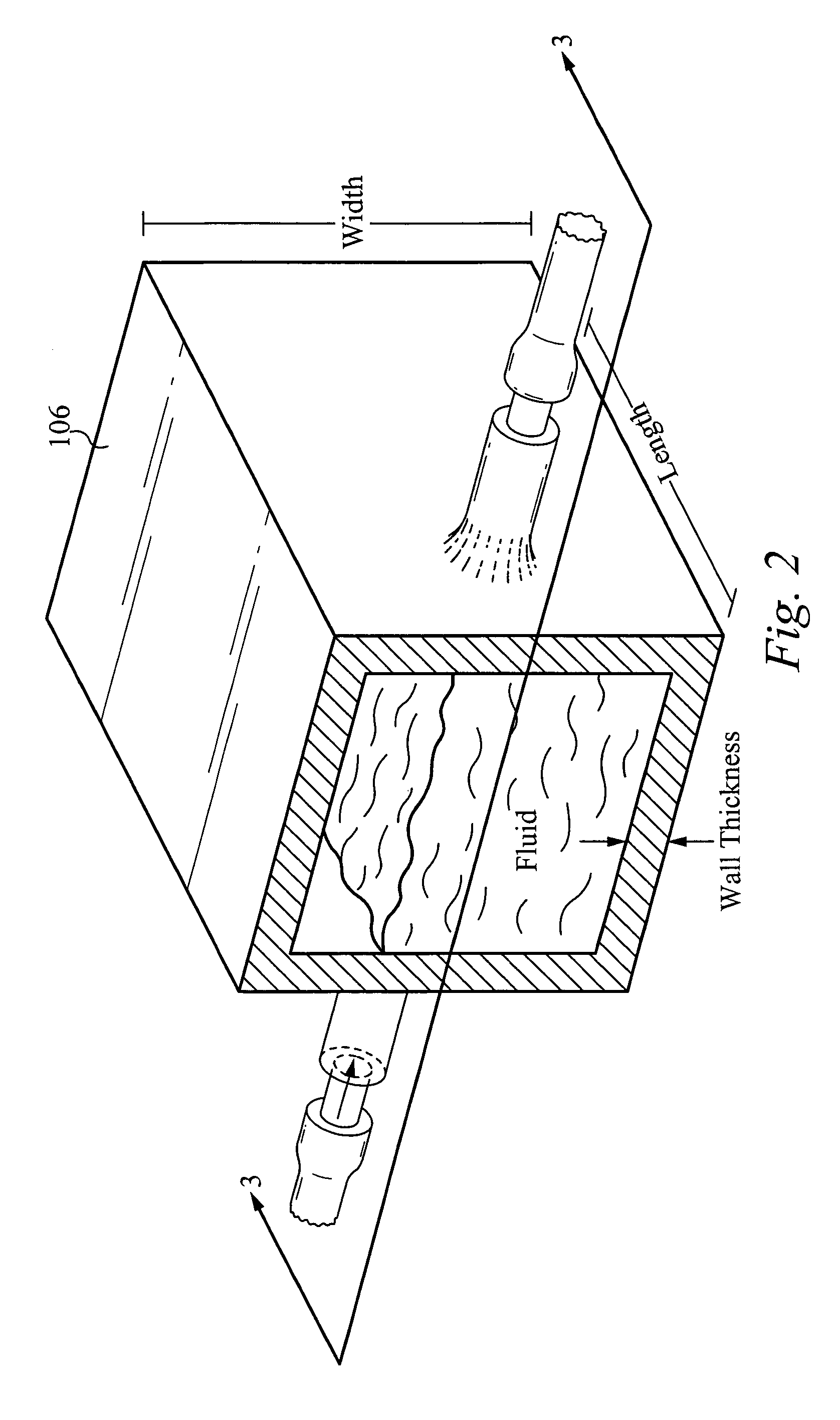
[0022]FIG. 1 illustrates a block diagram of a hermetic closed loop fluid system 100 in accordance with the present invention. As shown in FIG. 1, the hermetic closed loop system 100 preferably cools an electronic device 99 such as a computer microprocessor. The fluid system 100 preferably includes at least one pump 106, at least one heat exchanger 102 and at least one heat rejector 104. As shown in FIG. 1, the heat exchanger 102 is coupled to the heat rejector 104 by one or more fluid lines 108. In addition, the heat rejector 104 is coupled to the pump 106 by one or more fluid lines 108. Similarly, the pump 106 is coupled to the heat exchanger 102 by one or more fluid lines 108. It is apparent to one skilled in the art that the present system 100 is not limited to the components shown in FIG. 1 and alternatively includes other components and devices.

[0023]The purpose of the hermetic closed fluid loop 100 shown in FIG. 1 is to capture heat generated by the electronic device 99. In pa...


PUM


Abstract

A hermetic closed loop fluid system for controlling temperature of a heat source includes at least one component including at least one heat exchanger in contact with the heat source. The heat exchanger is configured to pass a fluid therethrough, wherein the fluid performs thermal exchange with the heat source. A predetermined amount of the fluid remains within the fluid system for a desired amount of operating time. The desired amount of operating time is preferably at least 10 years. Alternatively, the desired amount of operating time is at least 3 years. The predetermined amount of fluid is preferably ninety percent of an initial amount of fluid. Alternatively, the predetermined amount of fluid is seventy five percent of an initial amount of fluid. Still alternatively, at least fifty percent of the fluid can remain within the fluid system for the desired amount of operating time. The fluid can be a single phase fluid. The fluid can also be a two phase fluid.

Description

RELATED APPLICATION[0001]This Patent Application claims priority under 35 U.S.C. 119(e) of the U.S. Provisional Patent Application, Ser. No. 60 / 489,730 filed Jul. 23, 2003, and entitled “PUMP AND FAN CONTROL APPARATUS AND METHOD IN A CLOSED FLUID LOOP”. The Provisional Patent Application, Ser. No. 60 / 489,730 filed Jul. 23, 2003, and entitled “PUMP AND FAN CONTROL APPARATUS AND METHOD IN A CLOSED FLUID LOOP” is also hereby incorporated by reference.FIELD OF THE INVENTION[0002]The invention relates to a fluid circulating system in general, and specifically, to a hermetic closed loop fluid system.BACKGROUND OF THE INVENTION[0003]Many heating and cooling systems are used in all aspects of industry to regulate the temperature of a heat source, wherein the fluid systems are closed loop and are sealed to prevent substantial leakage of working fluid from the system. Existing heating and cooling fluid systems use flexible hoses, gaskets, clamps, and other seals to attempt to provide a sealed...

Claims


Application Information

Patent Timeline
Patent Type & Authority Patents(United States)
IPC IPC(8): F28D15/00H01L23/473
CPCH01L23/473H01L2924/09701H01L2924/0002H01L2924/00
Inventor WERNER, DOUGLASMUNCH, MARKKENNY, THOMAS
Owner VERTIV CORP
Learn More