Method and apparatus for removing casing

a casing and casing technology, applied in the field of oil and gas wells, can solve the problems of reducing the drilling time and reducing the drilling speed of the drill bit, so as to avoid fire risks and reduce the drilling time

Inactive Publication Date: 2006-04-04
HUDSON SERVICES
View PDF12 Cites 14 Cited by
  • Summary
  • Abstract
  • Description
  • Claims
  • Application Information

AI Technical Summary

Benefits of technology

[0012]The apparatus of the present invention solves the problems confronted in the art in a simple and straightforward manner. Provided is a method and apparatus for removing casing from a well bore. More specifically, the present invention solves the above problems by having a plurality of drills and a collar system for drilling two holes whereby the drills can be aligned with each other. Additionally, both holes can be drilled substantially simultaneously reducing drill time.
[0013]Both drills can be pneumatically powered to avoid fire risks. The drills can be mounted on a collar which is attached to the casing to be drilled. After both holes are drilled a bar can be placed through the two holes and a collar attached to the bar. The collar can be attached to the rig's top drive unit or draw works and the casing pulled an incremental amount, such as forty feet. The incremental amount pulled can vary by rig size, rig components, operator preference—and can change from pull to pull. For example, an incremental amount pulled can vary from five feet to ninety feet. After being pulled and cut, the incremental section of casing can be properly disposed of.
[0014]Drill bits can be sized to allow the bits to go completely through very thick portions of casing with cement layers attached thereon—drilling to the casing's interior without periodically cleaning / emptying the drill bits. Additionally, during the drilling process, the bits can be lubricated with fluid, such as by water, to prevent sparks and cooling thereby allowing drilling to continue all the way through the cement and casing thickness without stopping for cooling down / cleaning out periods.
[0015]The present invention provides a more efficient operation significantly improving the speed and safety of removing casing from a well bore.

Problems solved by technology

Removing the casing is a difficult job because of the tremendous amount of force which must be placed on the casing to pull it out of the ground.
This process would take much time and slow down the removal of the casing (such as 2 hours).
This process took much rig time and created a hazardous working environment when using a torch and was potentially repeated for each incremental section of casing.

Method used


Image

  • Method and apparatus for removing casing
  • Method and apparatus for removing casing
  • Method and apparatus for removing casing

Examples


Embodiment Construction

[0022]Detailed descriptions of one or more preferred embodiments are provided herein.

[0023]It is to be understood, however, that the present invention may be embodied in various forms. Therefore, specific details disclosed herein are not to be interpreted as limiting, but rather as a basis for the claims and as a representative basis for teaching one skilled in the art to employ the present invention in any appropriate system, structure or manner.

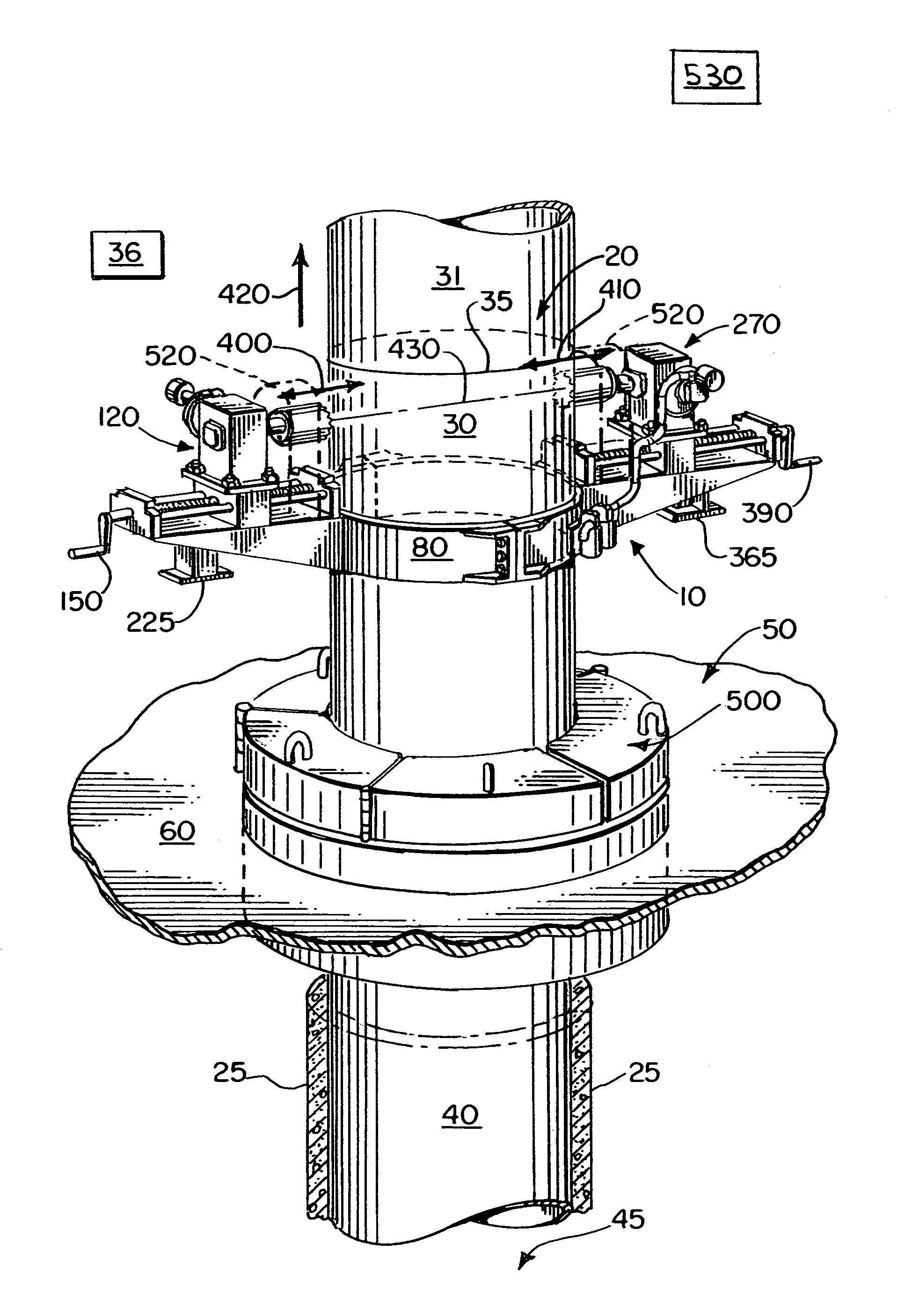
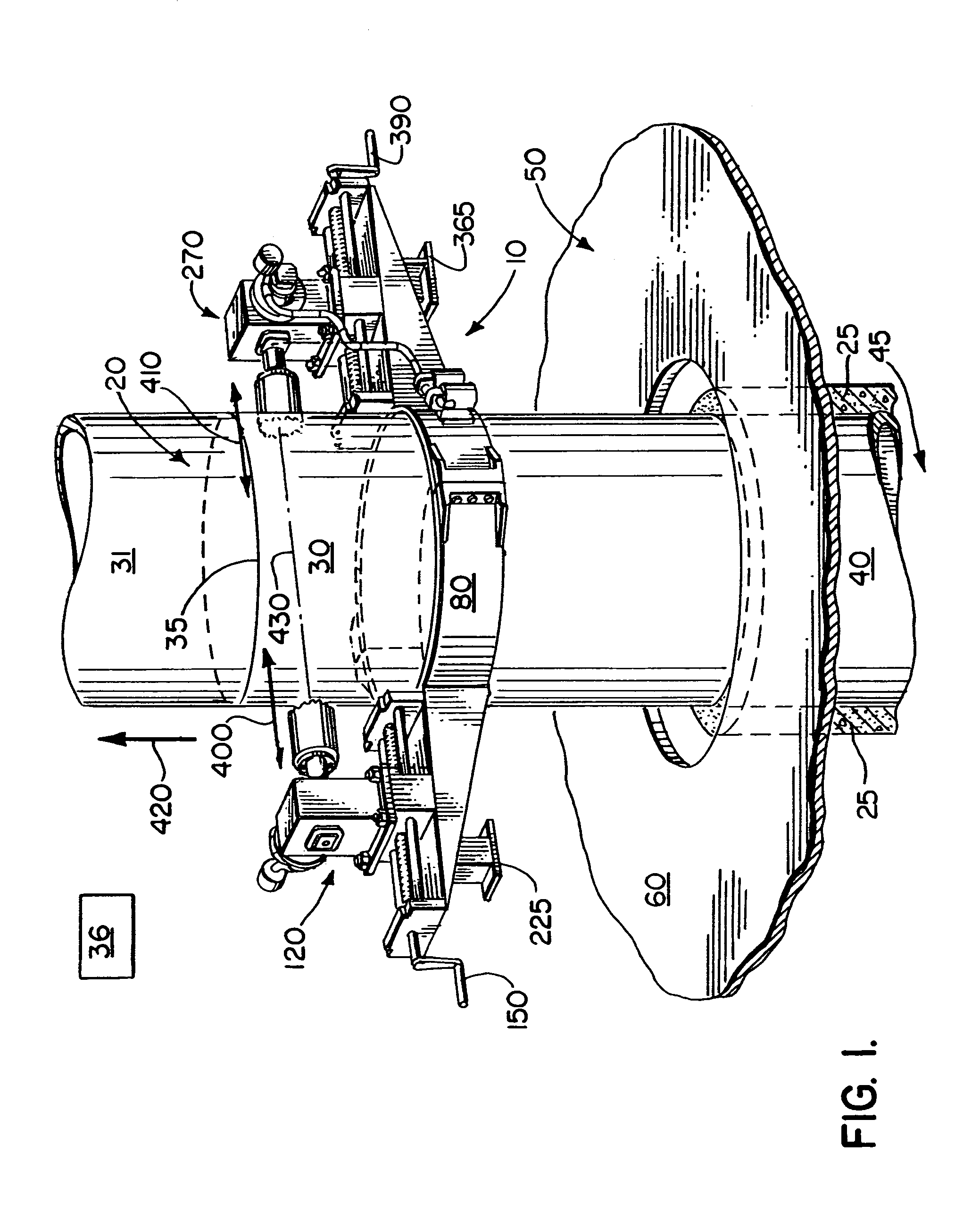
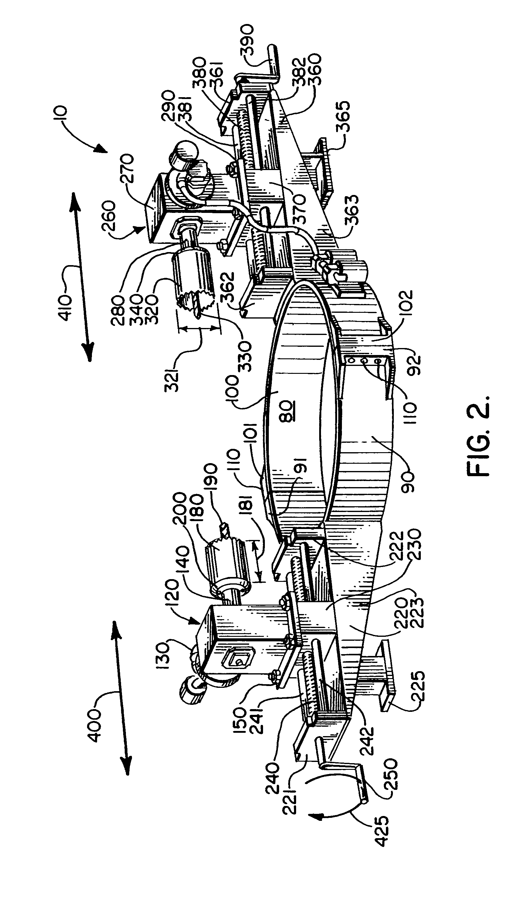
[0024]It will be understood that such terms as “up,”“down,”“vertical” and the like are made with reference to the drawings and / or the earth and that the devices may not be arranged in such positions at all times depending on variations in operation, transportation, and the like. As well, the drawings are intended to describe the concepts of the invention so that the presently preferred embodiments of the invention will be plainly disclosed to one of skill in the art but are not intended to be manufacturing level drawings or renditions of fi...


PUM


Abstract

A method and apparatus for removing a string of casing from a well bore. The method and apparatus include a plurality of drill bits substantially aligned with each other for drilling a plurality of holes in the string of casing. The plurality of holes can be used to lift the string in casing from the well bore via a series of incremental casing sections.

Description

CROSS-REFERENCE TO RELATED APPLICATIONS[0001]Not applicableSTATEMENT REGARDING FEDERALLY SPONSORED RESEARCH OR DEVELOPMENT[0002]Not applicable[0003]REFERENCE TO A “MICROFICHE APPENDIX”[0004]Not applicableBACKGROUND[0005]The present invention relates generally to oil and gas wells and, more specifically, to a system for removing casing which has been placed in a well bore.[0006]The process of drilling subterranean wells to recover oil and gas from reservoirs, consists of boring a hole in the earth down to the petroleum accumulation in the reservoir, and installing pipe from the reservoir to the surface. Casing is a protective pipe liner within the well bore that is cemented in place to ensure a pressure-tight connection to the oil and gas reservoir. The casing can be run from the rig floor as it is lowered into the well bore. After the casing has been run to the desired depth it is typically cemented within the well bore. The purpose of cementing is to seal the casing to the well bor...

Claims


Application Information

Patent Timeline
Patent Type & Authority Patents(United States)
IPC IPC(8): E21B29/08E21B19/16
CPCE21B29/10E21B19/06
Inventor REMEDIES, SANDRARUCKER, JOHNBLANCHARD, RICHARDDESLATTE, DONALD D.CAHILL, KENNETH
Owner HUDSON SERVICES
Why Eureka
Try Eureka