Bi-directional ball seat system and method

a technology of a ball seat and a directional ball, which is applied in the direction of fluid removal, sealing/packing, and wellbore/well accessories, etc., can solve the problems of not being actively captured, unable to restrict the ball or other device, and unable to construct a remote restraining device in the reverse direction

Inactive Publication Date: 2006-04-04
BAKER HUGHES INC
View PDF13 Cites 171 Cited by
  • Summary
  • Abstract
  • Description
  • Claims
  • Application Information

AI Technical Summary

Benefits of technology

[0015]The invention also provides a method of using a fluid control system for a hydrocarbon well, the control system comprising a first portion having an actuator, an inner sleeve slidably disposed with the first portion and forming a longitudinal passageway, a seat coupled to the control system and exposed to the passageway, and a radial protrusion disposed at least partially in the inner sleeve and exposed to the passageway with the seat, the method comprising using the control system in a location associated with the well with the radial protrusion retracted from the passageway; allowing a movable restriction to engage the seat; and moving the inner sleeve relative to the first portion to cause the actuator of the first portion to extend the radial protrusion into the passageway to selectively restrict the longitudinal travel of the movable restriction between the radial protrusion and the seat.

Problems solved by technology

However, one issue that has remained problematic is how to restrict the ball or other device from reversing up the passageway from the direction in which it entered the passageway once it has been placed on the ball seat.
Because the ball is typically inserted into a tubing passageway and generally flows downstream in the passageway to a remote site that has the ball seat, it has heretofore been difficult to construct a remote restraining device in the reverse direction.
First, the ball is not actively captured.
The shoulder's ability to restrict a reverse travel is limited and does not correspond with the general strength of the tool to withstand various operating pressures.
However, similar problems occur in this type of seat.
The reversal control ability is simply dependent upon the original size and configuration, and thus the reverse control capabilities of the tools are limited.

Method used


Image

  • Bi-directional ball seat system and method
  • Bi-directional ball seat system and method
  • Bi-directional ball seat system and method

Examples


Embodiment Construction

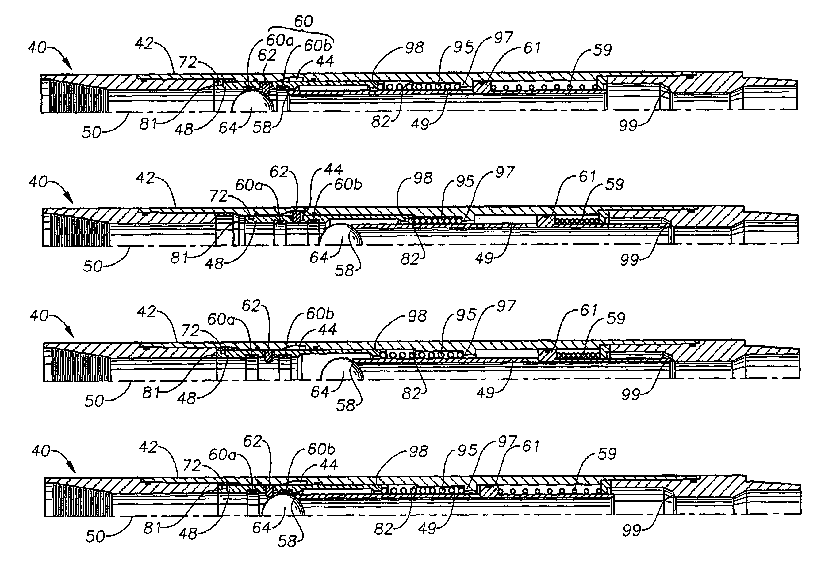
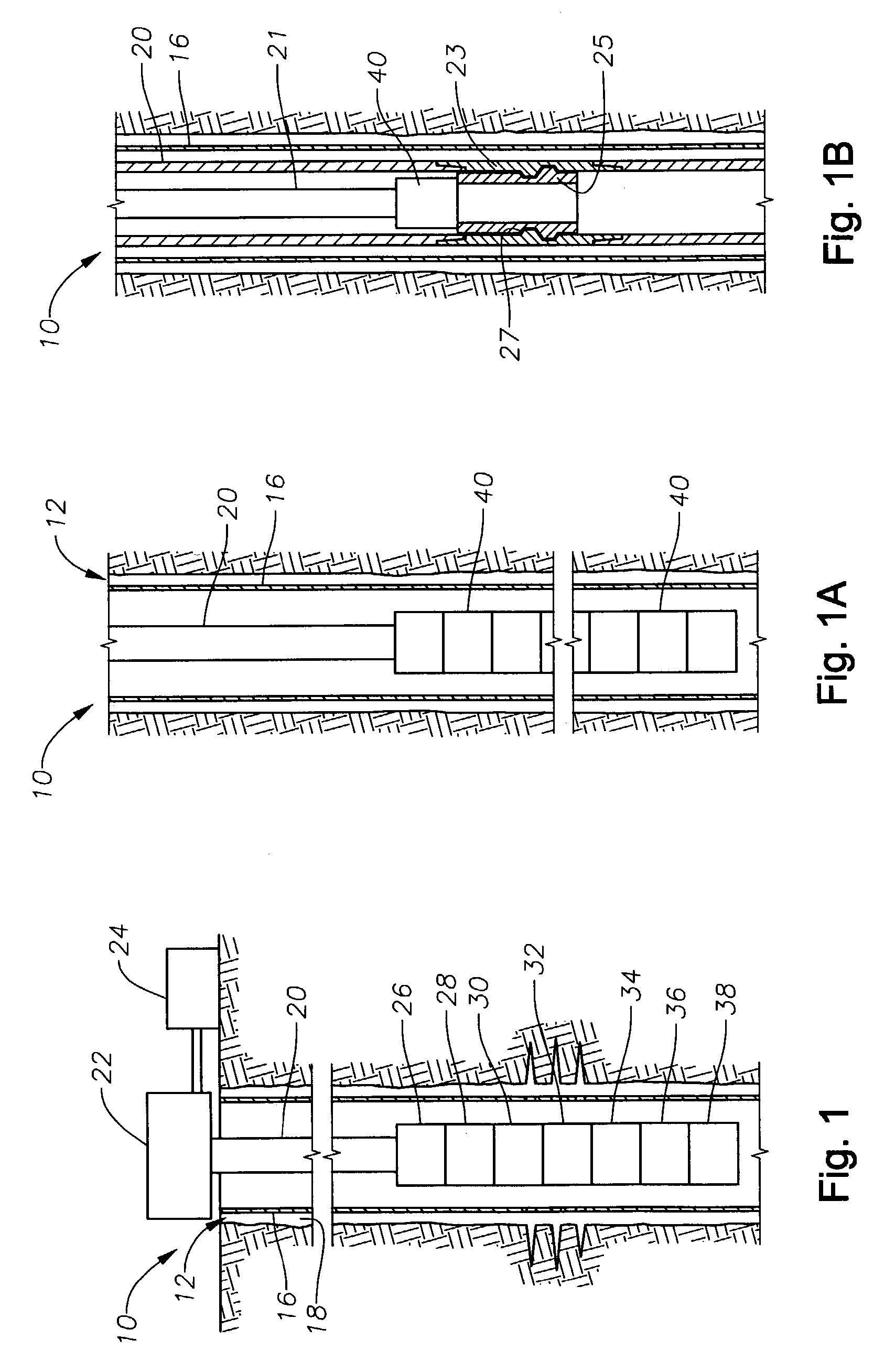
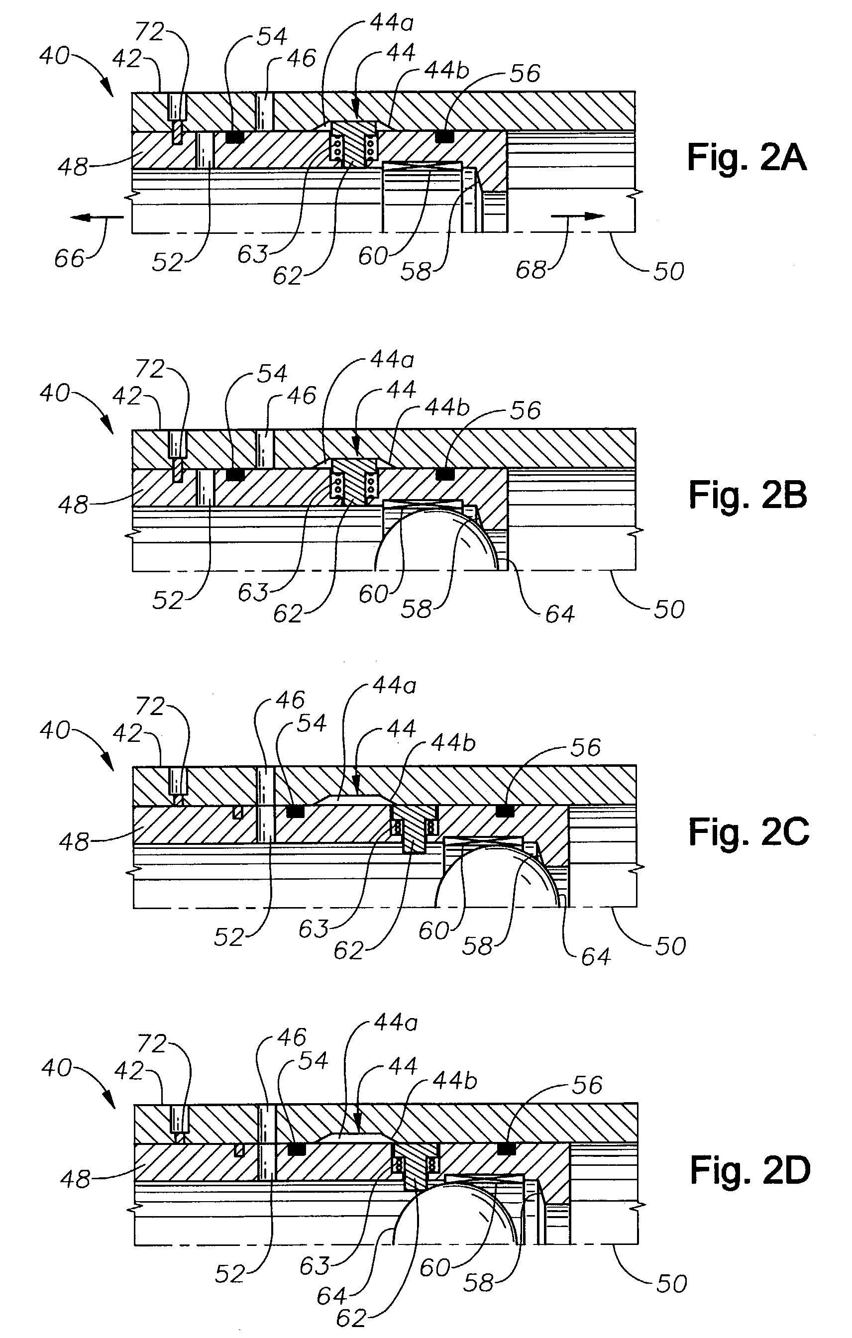
[0053]FIG. 1 is a schematic cross-sectional view of a well with various tools disposed therein. A well 10 is generally used to recover below-surface minerals such as gas, oil, and other minerals, hereinafter termed “hydrocarbons.” Generally, a well bore 12 is formed in the surface of the ground or subsea layers 14. A casing 16 is normally inserted in the well bore 12, when the well bore has been drilled to a certain desired depth. An annulus 18 between the casing and the well bore 12 is generally filled with a cement-like substance. A tubular string 20 is inserted in the casing 16. The tubular string can be a completion string, coiled tubing, a production string, wireline, and other members that are inserted down the casing 16 for different processes used to ultimately extract the hydrocarbons from the underlying layers through which the well bore is formed. Various equipment can be attached directly or indirectly to the tubing string below or above the surface. For example, a blow-...


PUM


Abstract

The present invention provides a bi-directional ball seat and method of use. In at least one embodiment, the present invention provides a fluid control system that includes a radial protrusion that can be selectively engaged and disengaged upstream and/or from a ball seat. For example, a ball can be placed in a passageway, engaged with a downstream ball seat, and the radial protrusion radially extended into the passageway distally from the seat relative to the ball. A reverse movement of the ball is restricted by the active radial movement of the radial protrusion into the passageway. The control system can be used to control a variety of tools associated with the well. Without limitation, the tools can include crossover tools, sleeves, packers, safety valves, separators, gravel packers, perforating guns, decoupling tools, valves, and other tools know to those with ordinary skills in the art.

Description

FIELD OF THE INVENTION[0001]This invention relates to hydrocarbon well devices and processes. More specifically, the invention relates to a control system for controlling fluid flow and actuating various tools associated with hydrocarbon wells.BACKGROUND OF THE INVENTION[0002]Typical hydrocarbon wells, whether on land or in water, are drilled into the earth's surface to form a well bore. A protective casing is run into the well bore and the annulus formed between the casing and the well bore is filled with a concrete-like mixture. Several types of tools are run into the casing for the various procedures used to complete and subsequently produce hydrocarbons from the well. Some of these procedures include perforating the casing and the concrete-like mixture. The perforating process creates channels into production zones of the earth at appropriate depths to allow the hydrocarbons to flow from the production zone through the casing and into production tubing for transport to the surfa...

Claims


Application Information

Patent Timeline
Patent Type & Authority Patents(United States)
IPC IPC(8): E21B34/14E21B34/06
CPCE21B34/14E21B34/06E21B34/142
Inventor BISHOP, FLOYD ROMAINETRAWEEK, MARVIN BRYCEROSS, RICHARD J.WALKER, DAVID J.TURNER, DEWAYNE M.
Owner BAKER HUGHES INC
Why Eureka
Try Eureka