Cable traction apparatus and method

a cable traction and cable technology, applied in the direction of rope railways, hoisting equipment, transportation and packaging, etc., can solve the problems of 0.7 and is generally not able to be dramatically increased, and achieve the effect of high force, reduced number of parts required, and high normal for

Inactive Publication Date: 2006-04-04
ELLINGSON DAVID IRWIN
View PDF16 Cites 32 Cited by
  • Summary
  • Abstract
  • Description
  • Claims
  • Application Information

AI Technical Summary

Benefits of technology

[0009]The moving chain links have a concave surface that matches the radius of the cable. This allows the high normal force to be distributed over a larger area. The limiting factor for normal force is to not exceed the stress deformation limit of the cable that is resisting this force. The cable is surrounded with two or more links—thus exerting even pressure completely around the cable. The normal force is applied to the chain links through pressure rollers. The pressure rollers and links are staggered in such a way that the force of the pressure roller is always distributed over a substantial area on the cable. This allows a much higher normal force to be applied without damaging the cable. The rollers are biased with Belleville springs. These springs are adjustable and provide a very high force over a short range of movement.
[0010]The invention includes several unique features as part of the mechanism. The multiple chain drives surround the cable. The drive line to bring this power to the chains from a single engine is accomplished in a unique manner. A worm drive pinion is positioned in a manner to allow the cable to run through the center of this pinion. Multiple worm output gears (one for each chain drive) are driven by this worm drive pinion. This gearing method keeps the multiple chain drives synchronized and reduces the number of parts required. The synchronization is required to maintain the staggered links.
[0016]Heat is added to the cabinet to increase the temperature of the chain links and rollers. This is to aid in melting any ice on the cable and evaporate moisture.

Problems solved by technology

A reasonable clean steel to steel surface has a coefficient of friction of about 0.7 and is generally not able to be dramatically increased.

Method used


Image

  • Cable traction apparatus and method
  • Cable traction apparatus and method
  • Cable traction apparatus and method

Examples


Embodiment Construction

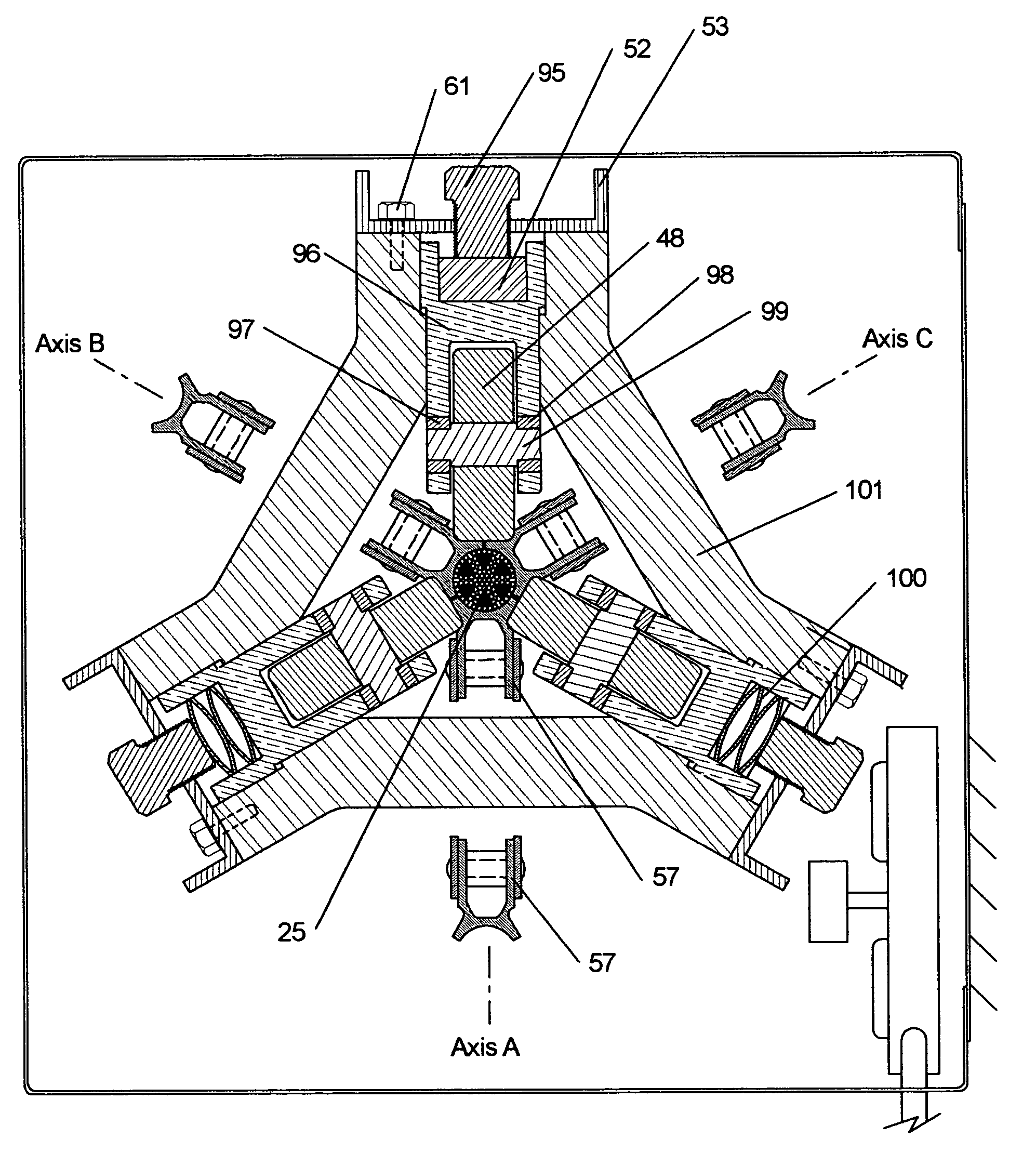
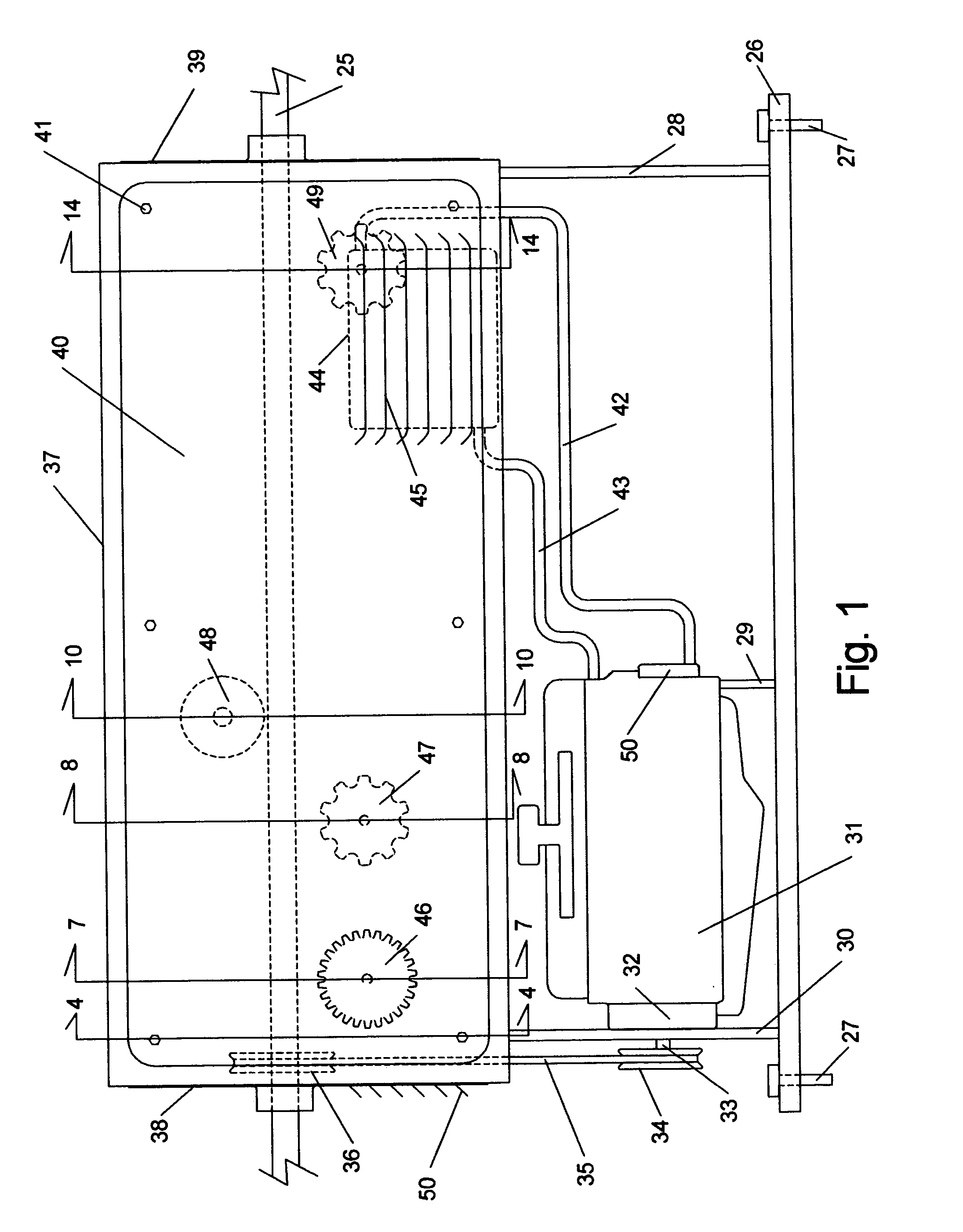
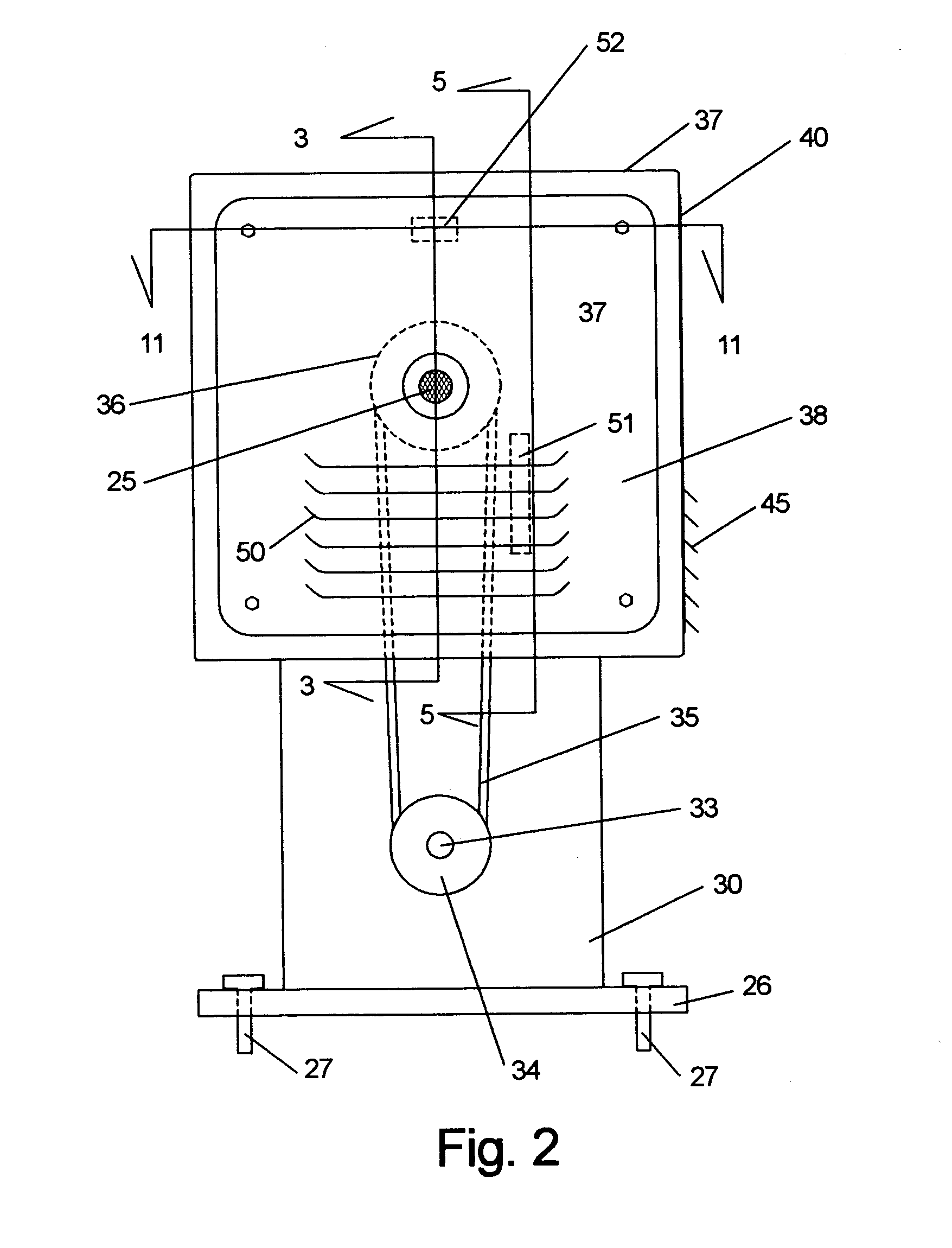
[0044]FIG. 1 shows the side view of the cable traction apparatus. The cable 25 enters and passes through the cable traction apparatus in a straight line. This cable could typically be a steel wire rope such as the AISI (American Iron and Steel Institute) standard 6x27H flattened strand (3 wire center) IWRC (independent wire-rope core) shown in FIG. 15. A cable is frequently mentioned, however the apparatus would provide traction to any reasonably rigid and reasonably constant cross section elongate member. Examples of this could include pipe, hose, dowel, or rope. Other non-circular cross sections would include a box-beam or hex-pipe. For a non-circular cross section, the cable link 86, shown in FIG. 8, would be shaped to match. The elongate member materials could include steel, aluminum, wood, copper and various multi-layer constructions. These shape and material examples are only representative and there are many others.

[0045]The base 26 provides support for the various mechanism ...


PUM


Abstract

A high force traction apparatus which operates along the cable linear axis with no cable bending. The cable is encircled with links from several looping chain drives. The links have a concave friction surface to match the cable radius. Rollers apply pressure to multiple links thereby providing a high normal force on the cable. The staggered and synchronized links keep the high squeeze force evenly distributed. This allows the traction apparatus to impose a pulling force that approaches the cable tensile limit without cable damage.

Description

CROSS-REFERENCE TO RELATED APPLICATIONS[0001]Not ApplicableFEDERALLY SPONSORED RESEARCH[0002]Not ApplicableSEQUENCE LISTING OR PROGRAM[0003]Not ApplicableBACKGROUND OF THE INVENTION[0004]This invention relates to the field of high force cable retraction means. Present devices generally utilize spool winding methods. These are limited in the amount of cable that can be retracted (only until the spool is full). Spool winding is also limited in maximum retraction force due to cable damage. The high force retraction causes excessive cable stress from bending and squeezing between the windings on the spool.[0005]Rotating sheaves such as used for elevators cannot provide high force retraction. Elevators overcome this deficiency with counterweights and by utilizing multiple cables.[0006]This invention further relates to a continuous cable pulling device (no limit on pulling length.) U.S. Pat. No. 4,256,199 granted to Sellards shows a serpentine device. This device is limited due to the hig...

Claims


Application Information

Patent Timeline
Patent Type & Authority Patents(United States)
IPC IPC(8): F16L1/12B65H20/00B65H23/08B61B7/06B66B9/02B66D1/00B66D3/00
CPCB61B7/06B66D3/003B66B9/02
Inventor ELLINGSON, DAVID IRWIN
Owner ELLINGSON DAVID IRWIN
Why Eureka
Try Eureka