Vapor-powered kinetic pump

a kinetic pump and kinetic pump technology, which is applied in the direction of positive displacement liquid engines, piston pumps, liquid fuel engines, etc., can solve the problems of low efficiency, loss of steam expansion energy, and inefficient use of gas energy, so as to reduce construction costs, reduce construction costs, and pump liquids efficiently

Inactive Publication Date: 2006-04-04
PRUEITT FAMILY TRUST S PRUEITT TRUSTEE
View PDF10 Cites 15 Cited by
  • Summary
  • Abstract
  • Description
  • Claims
  • Application Information

AI Technical Summary

Benefits of technology

[0018]The acceleration tube may be oriented at any angle and comprise a left piston and a right piston within the acceleration tube for placing separation distances between the vapor or gas and the liquid and for storing kinetic energy during acceleration by the vapor, the liquid being placed at a left of the left piston and at a right of the right piston. In this embodiment, the compressed-air surge tank preferably comprises two compressed-air surge tanks, one connected at a left end of the acceleration tube and another connected at a right end of the acceleration tube. The check valve then preferably comprises one or more flapper check valves on each end of the acceleration tube, and the inlet preferably comprises a first valve means at each end of the acceleration tube for admitting replacement liquid into the acceleration tube actuated by one of the pistons, and additionally comprising employing a second valve admitting the vapor or gas into the acceleration tube actuated by one of the pistons, a third valve releasing the vapor or gas from the acceleration tube, the third valve being closed mechanically by one of the pistons and being opened by hydraulic pressure from the liquid, and an air pipe at each end of the acceleration tube inserted into holes in centers of the left and right pistons and connected to the compressed-air surge tanks so that air pressure can accelerate the left and right pistons toward a center of the acceleration tube. A transfer piston near each end of the acceleration tube holds the liquid in place and transferring kinetic energy from the left and right pistons to the liquid, a stop ring near each end of the acceleration tube limits travel distance of the transfer pistons, and a check valve at each end of the acceleration tube admits replacement liquid into the acceleration tube.
[0019]A sealed cylinder may be employed surrounding a portion of the acceleration tube wherein the vapor or traverses, wherein a portion of the vapor or is allowed to flow into the sealed cylinder to supply heat to that portion of the acceleration tube to prevent condensation of the vapor or gas on interior walls of the acceleration tube.
[0021]It is therefore an object of the present invention to provide a direct gas-to-liquid pump that can pump liquids to very high pressures efficiently. The gas can be a vapor (such as steam) from a boiler, from an internal combustion process, or other source of high-pressure gas.
[0022]Another object of the present invention is to reduce the cost of construction of high-pressure pumps.

Problems solved by technology

The main problem with these and other patents that utilize a gas or vapor to push a liquid out of a tank is that they inefficiently use the energy in the gas.
When a valve is opened to release the steam, the energy of expansion of the steam is lost.
If the pressure in the storage tank is high, only the high-pressure portion of the combustion expansion will be effective, and the efficiency will be low.
Since the liquid is almost incompressible, if it has high velocity, it can build up high pressures when it is suddenly decelerated.

Method used


Image

  • Vapor-powered kinetic pump
  • Vapor-powered kinetic pump
  • Vapor-powered kinetic pump

Examples


Embodiment Construction

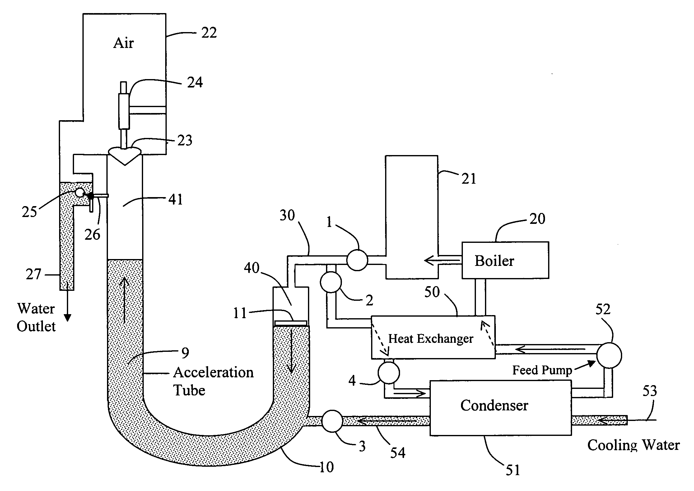
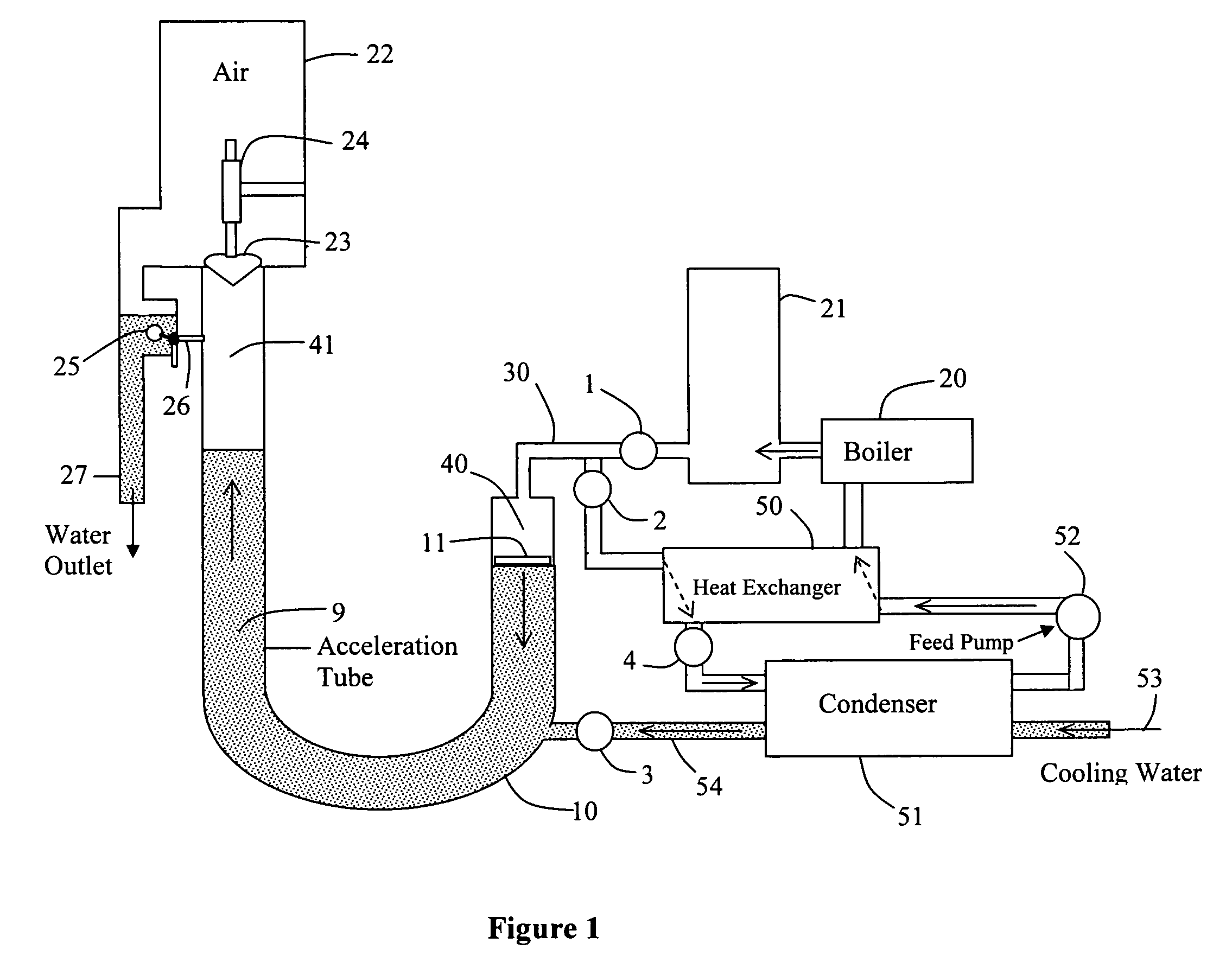
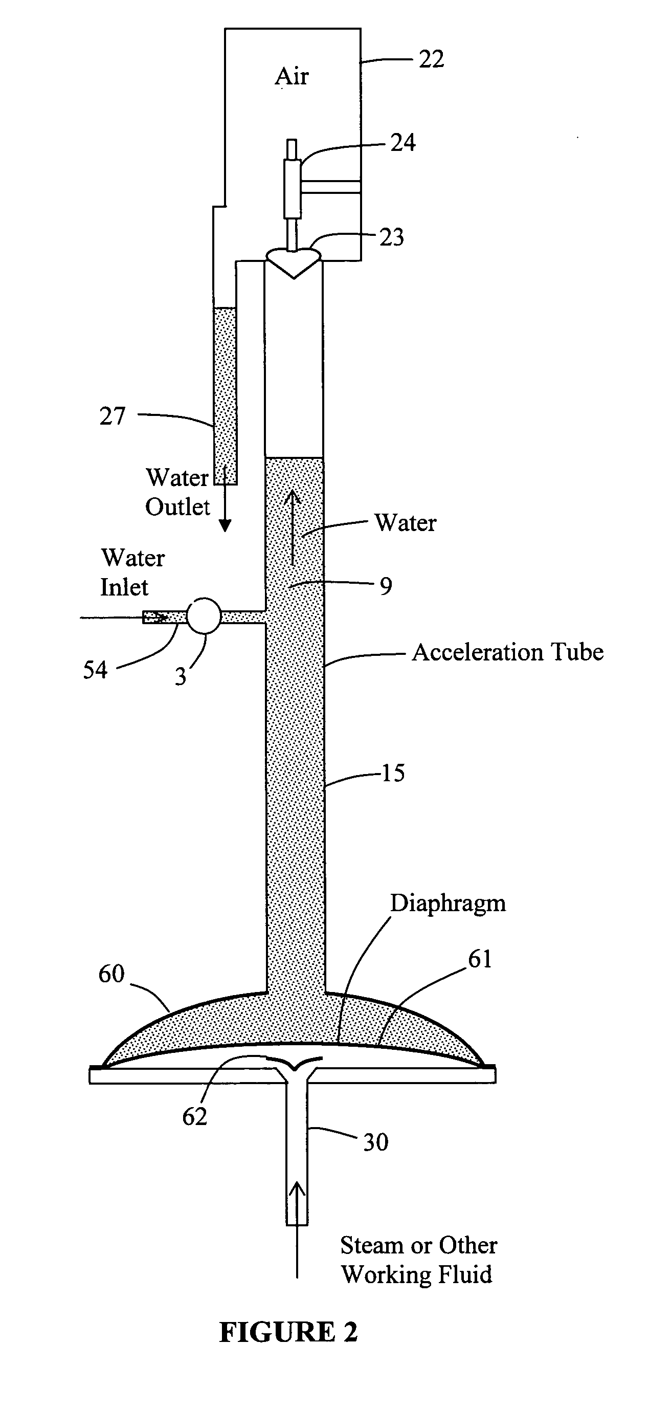
[0039]The present invention is of an apparatus and method that utilizes a pressurized vapor or gas to pump a liquid. The vapor enters an acceleration tube containing the liquid and forces the liquid to accelerate during a free run. The initial displacement of the liquid by the in-flowing vapor and the adiabatic expansion of the vapor contribute to the kinetic energy of the liquid, thus providing high pumping efficiency. When the liquid reaches the end of the acceleration tube, it strikes and opens a check valve so that the liquid flows into a compressed-air surge tank. The pressure in the surge tank can be considerably higher than the initial pressure of the vapor. The vapor can be supplied by a boiler heated by solar energy or other heat source. A pressurized gas can be supplied by internal or external combustion. The device can use relatively low-pressure vapor to pump high-pressure saline water into a reverse osmosis unit to produce fresh water. The device can also pump liquids f...


PUM


Abstract

A kinetic pump and method of pumping a liquid comprising providing an acceleration tube for the acceleration of a liquid contained therein by an introduced high-pressure vapor or gas, receiving the liquid from the acceleration tube with a compressed-air surge tank, admitting the liquid from the acceleration tube into the compressed-air surge tank via a check valve, draining the liquid from the compressed-air surge tank from an outlet, and adding additional liquid to the acceleration tube via an inlet, wherein during each first half cycle of the method, the vapor or gas forces the liquid to accelerate in the acceleration tube, whereby a portion of the liquid is forced into the compressed-air surge tank, and wherein during each second half cycle of the pump, the vapor or gas is substantially removed from the acceleration tube and the liquid flows back to its original location and the additional liquid is added to the liquid.

Description

CROSS-REFERENCE TO RELATED APPLICATIONS[0001]This application claims the benefit of the filing of U.S. Provisional Patent Application Ser. No. 60 / 509,975, entitled “Vapor-Powered Hydraulic Ram Pump”, filed on Oct. 8, 2003, and the specification thereof is incorporated herein by reference.STATEMENT REGARDING FEDERALLY SPONSORED RESEARCH OR DEVELOPMENT[0002]Not Applicable.INCORPORATION BY REFERENCE OF MATERIAL SUBMITTED ON A COMPACT DISC[0003]Not Applicable.COPYRIGHTED MATERIAL[0004]Not Applicable.BACKGROUND OF THE INVENTION[0005]1. Field of the Invention (Technical Field)[0006]The present invention relates to direct gas-to-liquid pump apparatuses and methods.[0007]2. Description of Related Art[0008]Hydraulic ram pumps have been used for many decades to pump small volumes of water to high pressures utilizing large volumes of water from low-pressure sources. In the process, much of the low-pressure water is discarded. More recently steam and other vapors have been proposed to pump wate...

Claims


Application Information

Patent Timeline
Patent Type & Authority Patents(United States)
IPC IPC(8): F04F1/06F04F1/04F04F7/02
CPCF04F7/02F04F1/04
Inventor PRUEITT, MELVIN L.JENSEN, REED J.JANZEN, ERNST C.
Owner PRUEITT FAMILY TRUST S PRUEITT TRUSTEE
Why Eureka
Try Eureka