Spinal interbody fusion device and method

a fusion device and spinal interbody technology, applied in the field of spinal interbody fusion device and method, can solve the problems of ineffective absorption of shock or support of spinal loads, time-consuming intraoperative preparation of bone graft blocks, and inability to effectively absorb shock or support spinal loads, etc., to achieve high friction coefficient, avoid injury to surrounding blood vessels, and resist translational and rotational movement

Inactive Publication Date: 2006-04-04
MASHBURN M LAINE
View PDF36 Cites 225 Cited by
  • Summary
  • Abstract
  • Description
  • Claims
  • Application Information

AI Technical Summary

Benefits of technology

[0010]The aforesaid and other objectives are realized by providing a vertically expandable spinal interbody fusion device of titanium alloy for surgically replacing a spinal disc. The device is designed for spinal disc space fusion and shock absorption as well as support and transmission of spinal loads while enhancing the replication of the physiological function of the spinal column.
[0014]The method as described results in a stable disc replacement with a secure interface between the plates of the spinal interbody fusion device and the horizontal surfaces of the adjacent vertebrae. Additionally, each plate has a roughened outer surface to create a high frictional coefficient with the vertebra in order to resist translational and rotational movement. Each plate moreover has an oval shape to conform to the horizontal configuration of an adjacent vertebra in order to avoid injury to surrounding blood vessels. Each plate diameter is significantly greater in area than the diameter of its corresponding shaft, defining a lever arm to produce a bending moment under spinal loads manifested by action of each plate. This flexing action generates opposing axial forces to replicate the normal physiological function of shock absorption, load bearing and load transmission.

Problems solved by technology

In lumbar disc replacement, static mesh cages fill and fuse the disc space but do not effectively absorb shock or support and transmit spinal loads.
Bone graft blocks have the additional disadvantage of time-consuming intraoperative preparation.

Method used


Image

  • Spinal interbody fusion device and method
  • Spinal interbody fusion device and method
  • Spinal interbody fusion device and method

Examples


Embodiment Construction

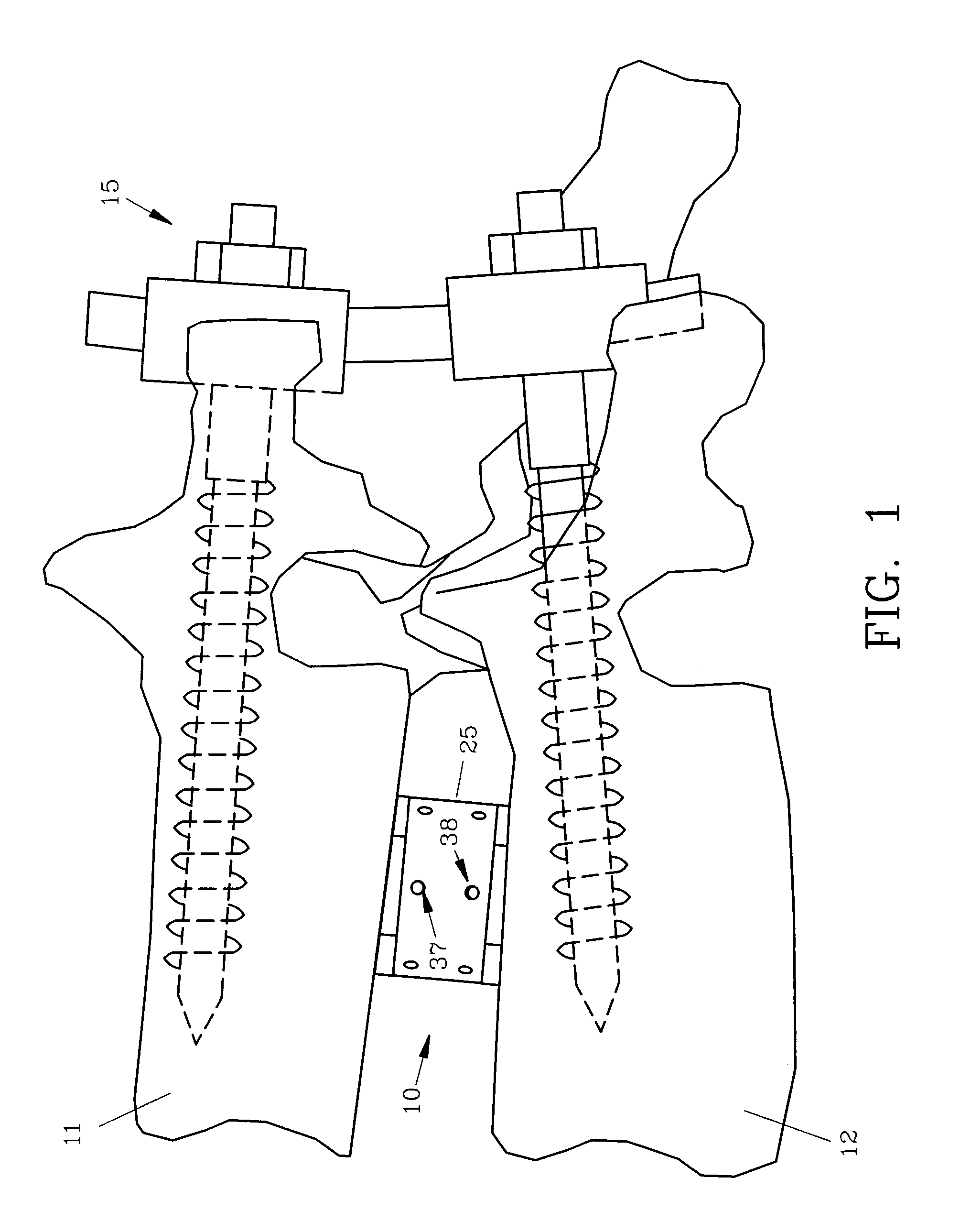
[0026]For a better understanding of the invention and its operation, turning now to the drawings, FIG. 1 illustrates preferred spinal interbody fusion device 10 in its fully contracted posture positioned between adjacent vertebra 11, 12. Conventional spinal fixation instrumentation 15 is also shown to contain the spine in a suitable posture after positioning and adjusting of fusion device 10.

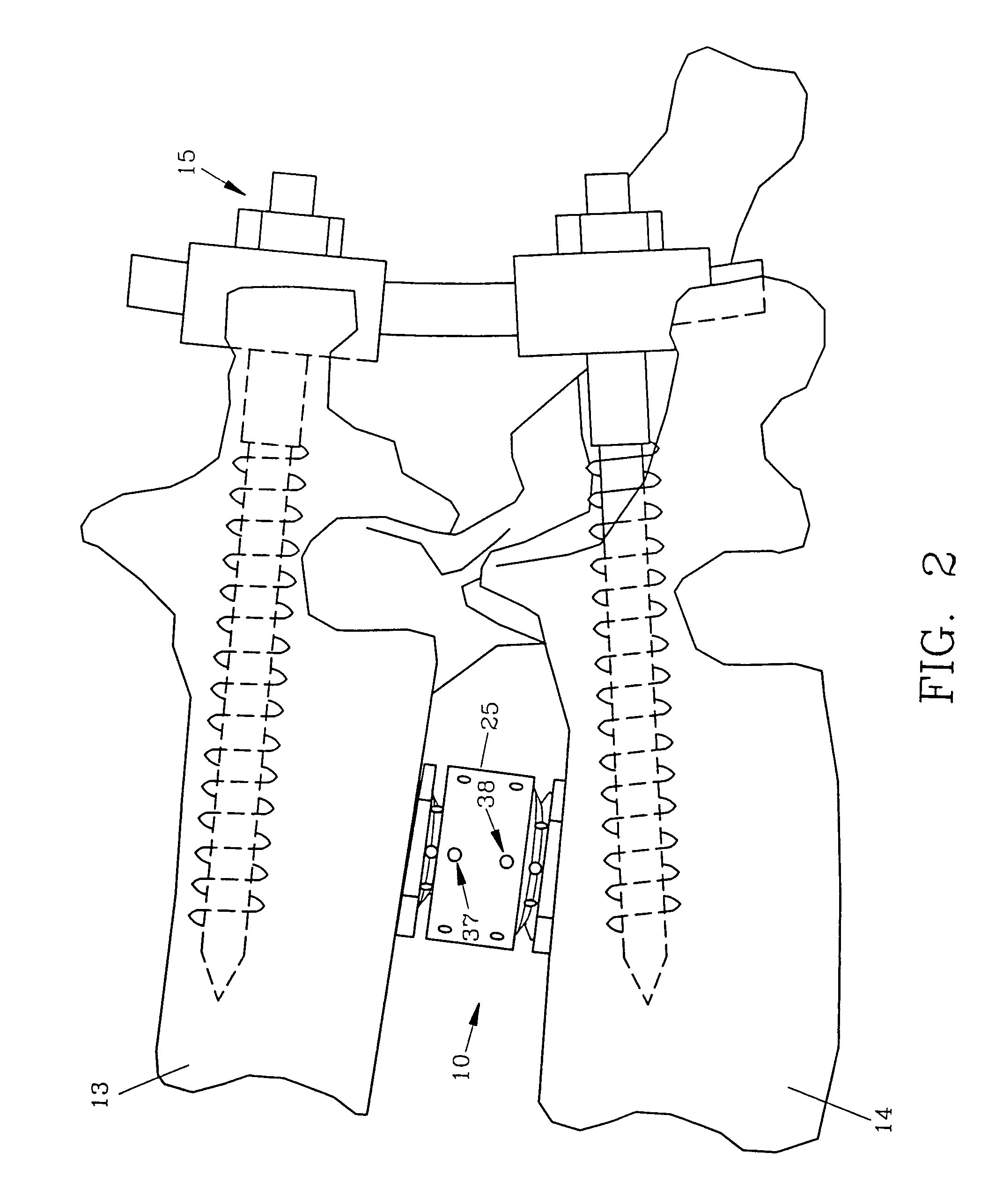
[0027]In FIG. 2, spinal interbody fusion device 10 is seen placed between another pair of vertebra 13, 14 which are spaced somewhat farther apart than those shown in FIG. 1, requiring fusion device 10 to be slightly expanded as will hereinafter be more fully described.

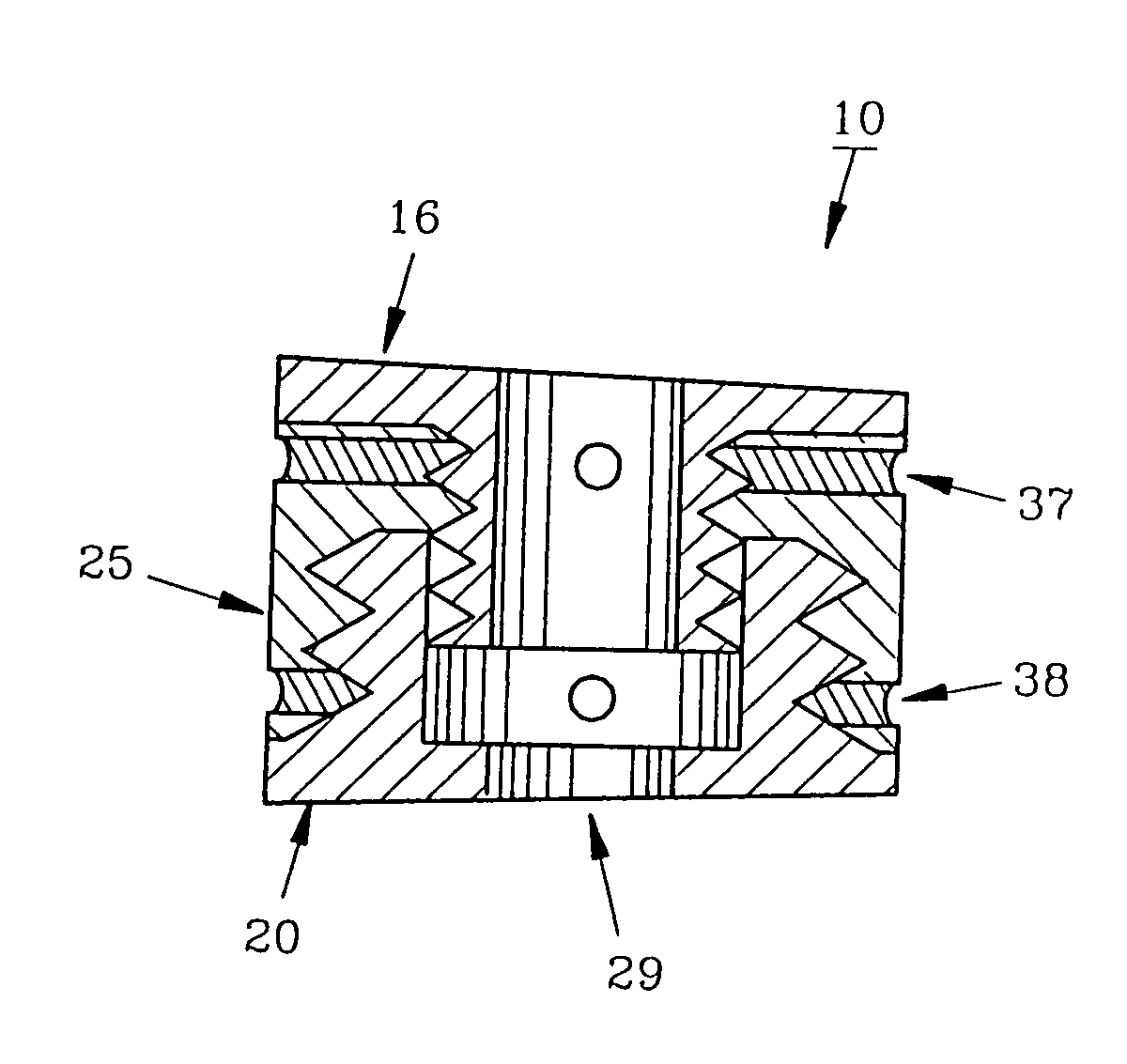
[0028]In FIG. 3, an enlarged view of fusion device 10 is shown in exploded fashion with upper or first plate 16 rigidly affixed to first threaded shaft 17, preferably having an outside diameter in the range of eleven (11) millimeters with an inside diameter of approximately seven (7) millimeters. Similarly, lower or second plate 20...


PUM

PropertyMeasurementUnit
diameteraaaaaaaaaa
diameteraaaaaaaaaa
diameteraaaaaaaaaa

Abstract

A disc replacement spinal interbody fusion device is provided having a central sleeve with oppositely left and right-hand threaded axial bores with different diameters. Circumferential threaded apertures are located on the sleeve and open into the sleeve bores. The device has two opposing plates which are oval-shaped and centrally, axially bored. Each plate has a perpendicular shaft with an axial bore which communicates with the plate bore. In situ, axial loading of the spinal column upon the fusion device creates a bending moment manifested by a flexing action of the plates to generate opposing axial directional forces which replicate the physiological function of shock absorption, load bearing and load transmission.

Description

FIELD OF THE INVENTION[0001]The present invention relates to a device and method designed to anatomically and physiologically replace a damaged spinal disc and to assist in fusing adjacent vertebra to stabilize the spine.DESCRIPTION OF THE PRIOR ART AND OBJECTIVES OF THE INVENTION[0002]The most appropriate technique currently used by spinal surgeons in the treatment of disc disorders is removal and replacement of an affected disc utilizing an anterior or anterolateral approach to the disc site. Removal of the disc causes an instability which must be corrected by disc replacement and bone grafting to restore the anatomical height and physiological function of shock absorption, load support and load transmission.[0003]Replacement materials currently favored are bone graft blocks or titanium mesh cages filled with disintegrated bone graft, both of which are held in place by anteriolateral or posterior fixation. In lumbar disc replacement, static mesh cages fill and fuse the disc space ...

Claims


Application Information

Patent Timeline
Patent Type & Authority Patents(United States)
IPC IPC(8): A61F2/44A61B17/70A61F2/00A61F2/28A61F2/30
CPCA61F2/4465A61B17/70Y10S606/907A61F2/442A61F2002/2835A61F2002/3041A61F2002/30507A61F2002/3055A61F2002/30561A61F2002/30563A61F2002/30601A61F2002/30785A61F2002/4475A61F2220/0025A61F2310/00407A61B17/7001A61F2002/30593
Inventor MASHBURN, M. LAINE
Owner MASHBURN M LAINE
Why Eureka
Try Eureka