Vacuum painting head and relative painting method

a vacuum painting and painting head technology, applied in the direction of spray nozzles, coatings, ion implantation coatings, etc., can solve the problems of inability to meet the requirements of vacuum painting head, inability to reduce the filter assembly of paint, and increased pressure inside the container, so as to prevent the paint from leaking and reduce the effect of the filter assembly

Inactive Publication Date: 2006-04-04
DELLE VEDOVE LEVIGATRICI
View PDF6 Cites 53 Cited by
  • Summary
  • Abstract
  • Description
  • Claims
  • Application Information

AI Technical Summary

Benefits of technology

[0017]Another purpose of the present invention is to achieve a vacuum painting head wherein the paint is in all cases prevented from leaking from the container when there is a break in supply of energy to the suction means intended to maintain the container in a depression, or vacuum.
[0024]Elastic means are provided to automatically take the stopper element to a rest position in which it hermetically closes the outlet aperture, thus preventing the paint from leaking out of the container.
[0025]With the painting head according to the present invention the following advantages, among others, are obtained: the paint introduced combines with the air which enters the container mainly through the outlet aperture through which the object exits, and is arranged in a constant and controlled turbulent flow, so that, when the stopper element is open, the profile is immersed in the paint and painting is carried out in a uniform manner; it is possible to not paint the leading end and / or trailing end of the object; less power is required for the suction pump which has to create the depression inside the container (from ⅓ to ⅕ of the power required in conventional painting heads); the filter assembly for the paint can be reduced with respect to that of conventional plants.
[0026]A further advantage of the painting head according to the present invention is that it can be directed and inclined as desired with respect to a working plane on which the object to be painted is rested.

Problems solved by technology

First of all, it does not allow to insert one profile at a time into the container, because the afore-said inlet and outlet apertures, when they are not partly obstructed by the profile, cause a sudden increase in the pressure inside the container, up to values near those of atmospheric pressure, with a consequent loss of paint through the apertures, due to the decrease in the suction effect.
Moreover, when the profile has the leading end and the trailing end already worked and shaped, for example to make the frame of a piece of furniture, a painting, a window or door frame or suchlike, and the leading end and / or the trailing end do not have to be painted, the conventional painting head is not able to meet this requirement.
A further disadvantage of the conventional painting head is that, in the event of a sudden interruption in the energy feeding the suction pump, with a consequent increase in the pressure inside the container, the paint contained therein exits uncontrollably from the inlet and outlet apertures, even if there is a profile being worked inside.

Method used


Image

  • Vacuum painting head and relative painting method
  • Vacuum painting head and relative painting method
  • Vacuum painting head and relative painting method

Examples


Embodiment Construction

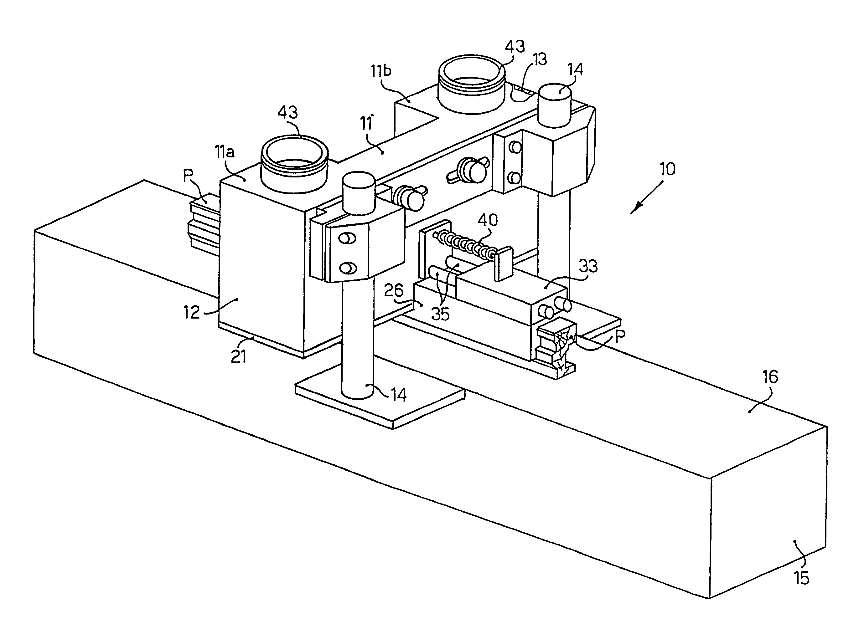
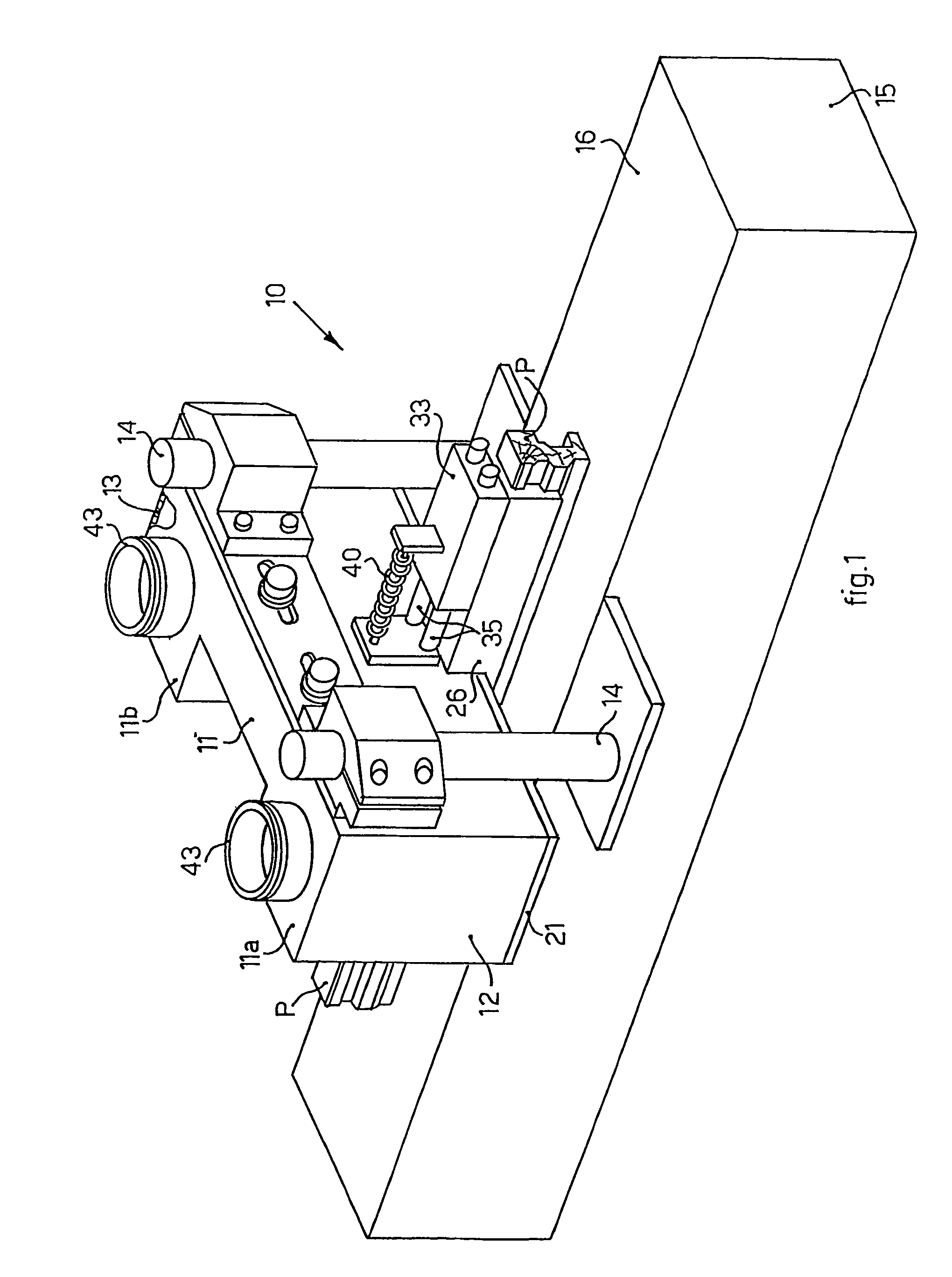
[0033]With reference to FIG. 1, a painting head 10 according to the present invention, to paint a profile P, comprises a container 11, substantially shaped like a parallelepiped, with two vertical protrusions 11a and 11b in correspondence with the lateral walls 12 and 13.

[0034]The painting head 10 is mounted on two vertical uprights 14 of a base 15, provided with a horizontal work plane 16. The distance between the painting head 10 and the work plane 16 is adjustable according to the profile P to be painted. The painting head 10, moreover, can be directed and inclined as desired, by means of any conventional means, with respect to the work plane 16 on which the profile P to be painted is rested.

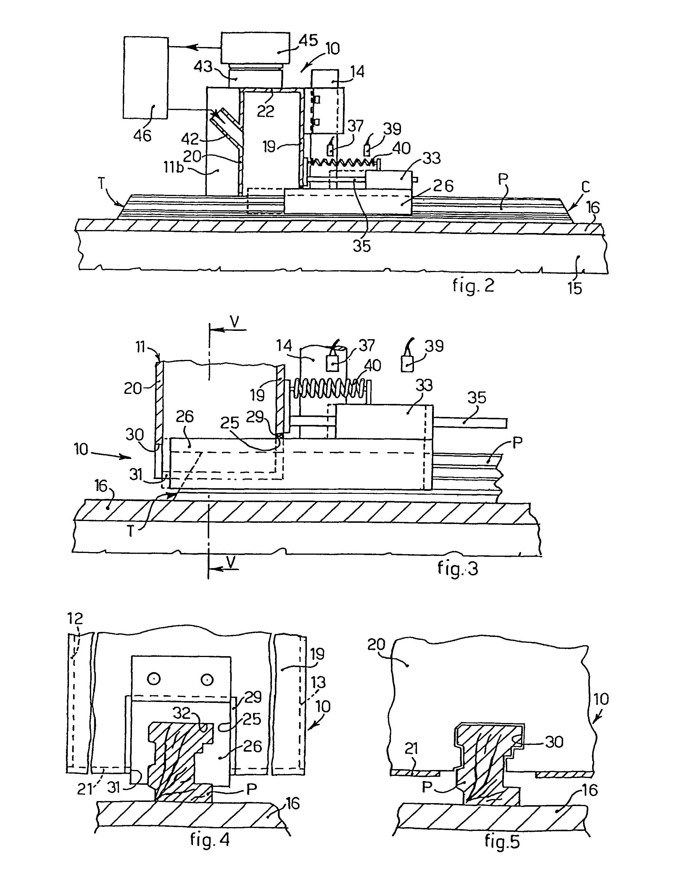
[0035]The container 11 also comprises a front wall 19 and a rear wall 20 (FIG. 2), parallel to each other, a bottom wall 21 and an upper wall 22.

[0036]On the front wall 19 there is an inlet aperture 25 (FIGS. 2 and 4) substantially rectangular in shape, in which a stopper element 26 is perman...


PUM

PropertyMeasurementUnit
speedaaaaaaaaaa
speedaaaaaaaaaa
atmospheric pressureaaaaaaaaaa

Abstract

A vacuum painting head to paint objects, including a container having an inlet aperture and an outlet aperture for the object to be painted, wherein the outlet aperture has a transverse section substantially equal to that of the object to be painted, wherein a suction pump is provided to create inside the container a determinate depression with respect to atmospheric pressure, and wherein paint is continuously introduced into the container. A stopper element is inserted into one of the apertures and is selectively movable to move away from or closer to the other aperture to open or close it.

Description

[0001]This application is a §371 National Stage Application of International Application No. PCT / IB02 / 02151, filed on 12 Jun. 2002, claiming the priority of Italian Patent Application No. UD 2002 A 000045 filed on 25 Feb. 2002.FIELD OF THE INVENTION[0002]The present invention concerns a vacuum painting head and the relative method to paint one or more surfaces of any object, whether it be a profile, a panel or otherwise, made of any material, such as wood, metal or plastic material. The painting head comprises a container having, on opposite and aligned sides, an inlet aperture and outlet aperture, through which the object to be painted is able to pass. Inside the container, in a continuous cycle, paint is introduced and air is sucked in; as it enters through the outlet aperture for the profile, the air mixes with the paint, which is thus sucked in towards the outside of the container together with the air. In particular objects, in order to prevent the paint in the container from g...

Claims


Application Information

Patent Timeline
Patent Type & Authority Patents(United States)
IPC IPC(8): B05C11/11B05B15/04B05B13/02B05B14/30B05B15/12B05B16/00
CPCB05B15/12B05B15/0425B05B15/0406B05B13/0207B05B14/30B05B16/00
Inventor DELLE VEDOVE, GAETANOBELLUZ, VITTORIO
Owner DELLE VEDOVE LEVIGATRICI
Why Eureka
Try Eureka