Seat control device for vehicle

a technology for controlling devices and seats, applied in the direction of electric devices, movable seats, transportation and packaging, etc., can solve the problems of deteriorating accessibility difficult to have access to the third-row seat through the second-row opening, and long time-consuming access to the third-row seat, so as to reduce the necessary time and improve the operation.

Inactive Publication Date: 2006-04-04
MAZDA MOTOR CORP
View PDF5 Cites 7 Cited by
  • Summary
  • Abstract
  • Description
  • Claims
  • Application Information

AI Technical Summary

Benefits of technology

[0006]The present invention has been devised in view of the above-described problems, and an object of the present invention is to provide a seat control device having excellent operation, in which ingress intention of a passenger who is supposed to sit on a second seat (for example, the third-row seat) that is behind a first seat (for example, t...

Problems solved by technology

Herein, in auto vehicles equipped with three rows of seats disposed in the longitudinal direction of the vehicle, such as van-type and wagon-type vehicles, if the second-row seat is located at a place where it is used normally, it is difficult to have access to the third-row seat through the second-row opening because of an existence of the second-row seat.
Namely, having access to the thi...

Method used


Image

  • Seat control device for vehicle
  • Seat control device for vehicle
  • Seat control device for vehicle

Examples


embodiment 1

Alternative Embodiment 1

[0111]Instead of the flow char of FIG. 13, the flow chart of FIG. 14 (Si (i=10, 11, 12 - - - ) denotes each step) is applicable. As shown in FIG. 14, starting condition of the control is the same as that in the flow chart of FIG. 13, and when the control starts and the full-open mode is selected (Yes in S10), firstly the sliding door 33 is driven backward to open fully (S11). Next, when the passenger does not sit on the third-row seat 5 (Yes in S12); the passenger does not sit on the second-row seat 4 (Yes in S13); and the child seat 26 is not installed on the second-row seat 4 (Yes in S14), the second-row seat 4 starts sliding forward (S15).

[0112]Even if the full-open mode is selected (Yes in S10), sliding forward of the second-row seat 4 is prohibited (S16) when the passenger sits on the third-row seat 5 (No in S12); the passenger sits on the second-row seat 4 (No in S13); and the child seat 26 is installed on the second-row seat 4 (No in S14). Further, whe...

embodiment 2

Alternative Embodiment 2

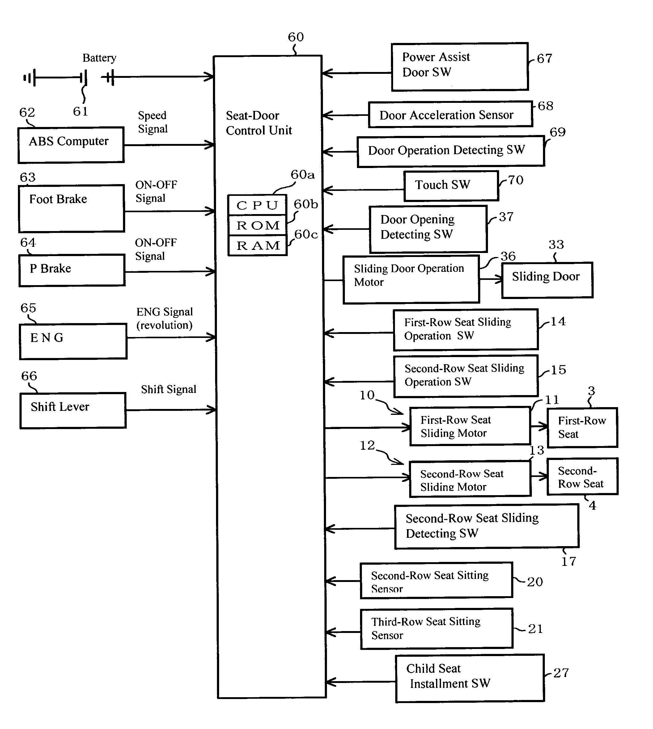
[0113]The sliding door 33 may be operated manually, omitting the door driving mechanism 35, and also the opening instruction operations 40, 45, 50, 55 may be omitted. In this case, the door opening detecting switch 37 for detecting the opening of the sliding door 33 is applied as the second-seat ingress prediction means. This control is executed by the flow chart (Si (i=20, 21, 22 - - - ) denotes each step) of FIG. 15. While the engine is ON, this control starts when the vehicle speed is at 0 km / h; the foot brake is ON or the parking brake is ON or the sift position is at parking range. On the other hand, while the engine is OFF, this control starts when a voltage of the battery 61 is equal to or more than a predetermined value. When the control starts and the sliding door 33 is opened (Yes in S20), it is determined based on the signal from the door opening detecting switch 37 whether the opening degree of the sliding door 33 is greater than the certain first...

embodiment 3

Alternative Embodiment 3

[0117]As shown in FIG. 16, the embodiment of the present invention may be configured such that a front step position detecting switch 85 is provided below a front scuff plate 80, which is a lower step located below the second-row ingress and egress opening 32, and a rear step position detecting switch 86 is provided below a rear scuff plate 81, which is a lower step located below the second-row ingress and egress opening 32, and a step position of the passenger is detected based on signals from the position detecting switches 85, 86. These step position detecting switches 85, 86 correspond to riding position detecting means for detecting ingress position of the passenger at the ingress and egress opening, and the ingress position detecting means is included by the above ingress position detecting means.

[0118]A piezoelectric element 88 that is disposed between a step base 82 and the respective scuff plates 80, 81 so that both faces thereof can contact them may...


PUM


Abstract

When ingress intention of a passenger who is supposed to sit on a second seat is predicted, a distance between a first seat and the second seat is expanded automatically. Accordingly, taking time for access to the second seat can be avoided, thereby decreasing necessary time for having access and improving accessibility to the second seat. When a full-open mode is selected (Yes in S1); the passenger does not sit on the third-row seat (Yes in S2); the passenger does not sit on the second-row seat (Yes in S3); and a child seat is not installed on the second-row seat (Yes in S4), a second-row seat sliding motor is driven and a first-row seat driving mechanism operates. Accordingly, forward sliding of the second-row seat starts (S5), and a sliding door is driven backward to open fully.

Description

BACKGROUND OF THE INVENTION[0001]The present invention relates to a seat control device for a vehicle, particularly to a seat control device in which a distance between a first seat and a second seat expands automatically when ingress intention of a passenger who is supposed to sit on the second seat exists.[0002]Conventionally, many types of auto vehicles equipped with two rows of seats disposed in a longitudinal direction of the vehicle are known, in which a first-row ingress and egress opening is disposed at a side of a first-row seat and a second-row ingress and egress opening is disposed at a side of a second-row seat. Generally, in van-type and wagon-type of auto vehicles equipped with three rows of seats disposed in the longitudinal direction of the vehicle, the first-row ingress and egress opening and the second-row ingress and egress opening are provided, but a third-row ingress and egress opening is not provided at a side of a third-row seat. Accordingly, passengers who ar...

Claims


Application Information

Patent Timeline
IPC IPC(8): B60N2/06B60N2/07B60N2/02B60N2/12
CPCB60N2/0248B60N2/123B60N2/067
Inventor ITAMI, YUKIHITOYAMASAKI, HIROKAZUOHTSUBO, TOMONORITAGUCHI, TOMOO
Owner MAZDA MOTOR CORP
Why Eureka
Try Eureka