Projection lens unit

a technology of projection lens and lens body, which is applied in the direction of electrographic process apparatus, mountings, instruments, etc., can solve the problems of heat loss, image on the screen may become blurred, and heat of the light source becomes an issue, etc., and achieves stable slide and high accuracy

Inactive Publication Date: 2006-04-04
SEKINOSU
View PDF4 Cites 6 Cited by
  • Summary
  • Abstract
  • Description
  • Claims
  • Application Information

AI Technical Summary

Benefits of technology

[0025]In the construction mentioned above, where the legs support the lens unit body at more than two places, compensation for the changes induced by thermal contraction or thermal expansion is achieved evenly at more than two places. However, when the lens unit body is supported at only two places, it is desirable that another member is provided to support the lens unit body so that the lens unit body can stably slide. It is also desirable that the legs are evenly spaced. When the legs are provided at more than three places to support the lens unit body, the lens unit body 6 can be stably supported by these three legs alone, and therefore no additional member is required to support the lens unit body. As described above, by supporting the projection lens unit body with the legs provided at more than three places, automatic compensation is achieved with high accuracy.

Problems solved by technology

However, in providing a high quality projection lens unit, the effect of heat becomes a problem.
When the projection lens unit is placed close to the light source, heat of the light source becomes an issue.
When these characteristics are changed in a projector or the like, the image on the screen may become blurred.
(1) When the inner tube 102 is shifted by thermal distortion of the bimetallic element 104, it moves while in slidable contact with the inner periphery of the outer tube 103 thereby generating a large amount of friction.
(2) While the inner tube 102 has appropriate dimensions for supporting the lenses 105, the diameter of the outer tube 103 is much larger than that of the inner tube 102 to accommodate the bimetallic element 104, thereby increasing the size of the projection lens unit 101.
(3) In the projection lens unit 101 of the above-mentioned construction, the inner tube 102 carrying the lenses 105 cannot be replaced and, therefore, there is no compatibility with other lenses.
(4) Where the inner tube 102 can move only within a limited range, the ability for compensation is limited.
(5) Because the inner tube 102, the outer tube 103, the bimetallic element 104, and the guide member 107 have a complicated construction, assembly thereof is difficult.
(6) Where only one bimetallic element 104 is provided between the inner tube 102 and the outer tube 103 it is not easy to accurately move the inner tube 102 and dimensional accuracy is difficult to achieve.
(7) Where the bimetallic element 104 does not easily transfer heat, the response for temperature compensation becomes poor.
However, in many cases, it is not possible to obtain a clear image by adjusting only one power lens because the effect of heat extends to various other components.

Method used


Image

  • Projection lens unit
  • Projection lens unit
  • Projection lens unit

Examples


Embodiment Construction

[0046]Referring now to the drawings, preferred embodiment of a projection lens unit according to the present invention will be described in detail below. In the following description, it is assumed that the projection lens unit is incorporated in a projector. Two embodiments of projection lens units will be described herein.

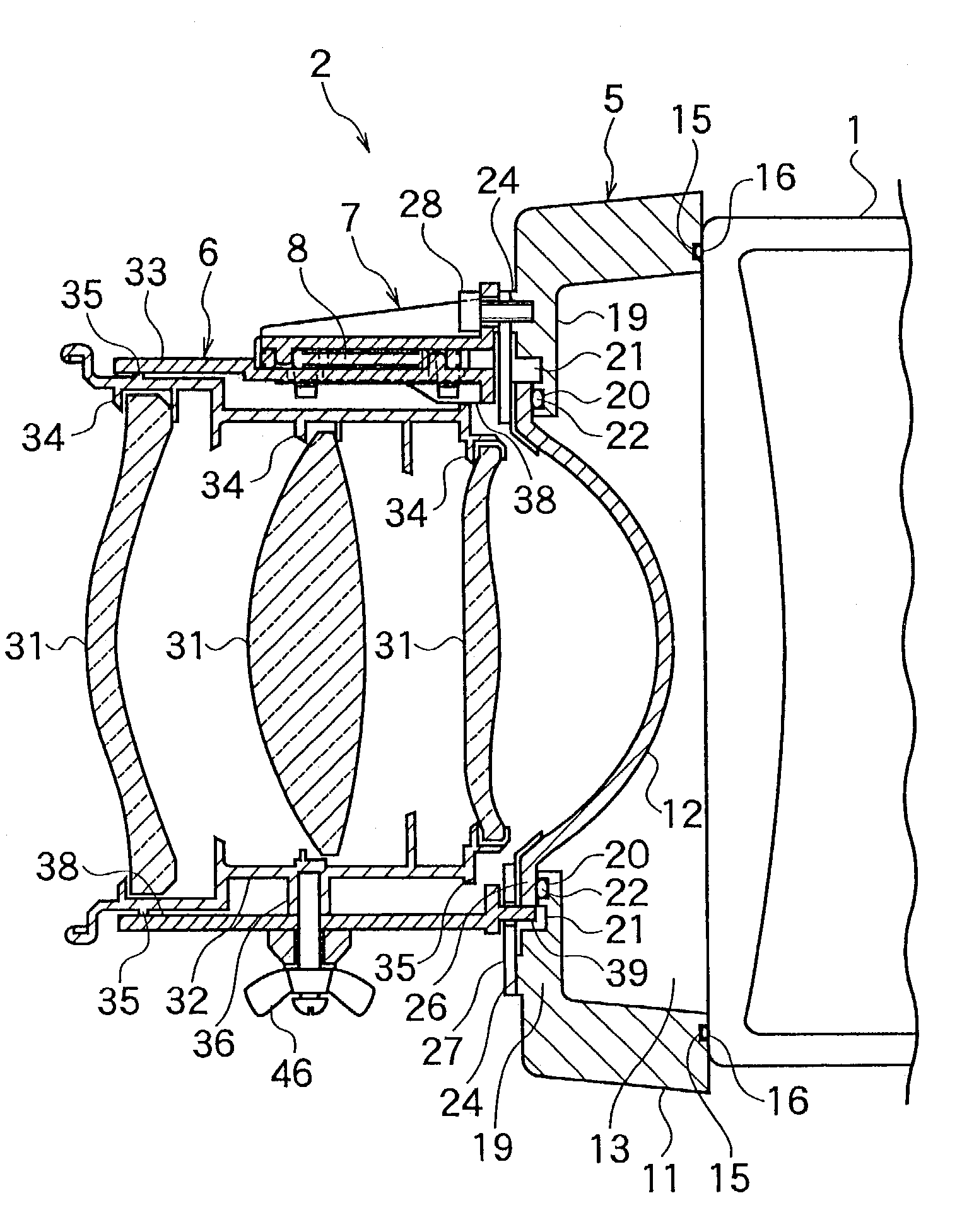
[0047]In a projector, an image which is formed by a CRT 1 is magnified by a projection lens unit 2 and projected onto a screen (not shown), as shown in FIG. 3 to FIG. 7. Accordingly, the projection lens unit 2 is directly fixed to the CRT 1. The CRT 1 and a coupler 5 of the projection lens unit 2 are integrally secured by CRT support fittings 3 (refer to FIG. 6). The front surface of the CRT 1 (left surface in FIG. 3) is formed as a flat plane on which the coupler 5 is mounted.

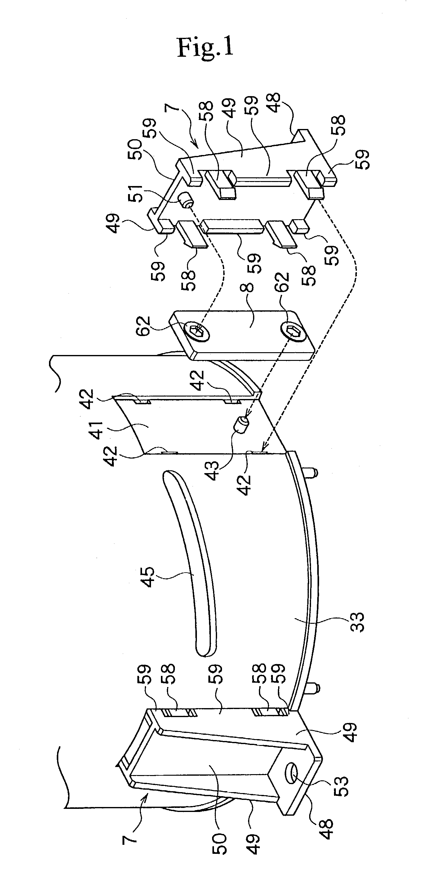
[0048]A first preferred embodiment of the projection lens unit 2 is shown in FIG. 3 and FIG. 4. The projection lens unit 2 projects an image, which has been formed by the CRT 1, onto a scre...


PUM


Abstract

A projection lens unit compensates for thermal expansion and contraction. The unit comprises a coupler at the front surface of a CRT, a lens unit body for projecting an image onto a screen by controlling and magnifying the light from the CRT, a plurality of legs secured to the coupler for supporting the lens unit body at more than three points, a slide mechanism (latch arms and latch engaging slots provided between the legs and the lens unit body for slidably supporting the legs for movement along the optical axis relative to the lens unit body, and expansion/contraction bars provided between the legs and the lens unit body for compensating for the thermally induced expansion/contraction, with one end engaged with a leg and the other end engaged with the base of the lens unit body.

Description

TECHINICAL BACKGROUD[0001]The present invention generally relates to a projection lens unit which is used in a projector and the like for projecting an image at the light source side onto a screen or the like, and, more specifically, to a projection lens unit provided with a function of automatically compensating for the effect of heat.[0002]In recent years, with demand for images of increasingly high definition from a projector and the like, consistent quality of the projected images (image quality) has become required. Accordingly, high performance is required of projection lens units. However, in providing a high quality projection lens unit, the effect of heat becomes a problem.[0003]When the projection lens unit is placed close to the light source, heat of the light source becomes an issue. The ambient temperature also has an affect on the quality. Specifically, thermal expansion and thermal contraction induced by heat of the light source and the ambient temperature change the ...

Claims


Application Information

Patent Timeline
Patent Type & Authority Patents(United States)
IPC IPC(8): G02B7/02G03G15/00G02B7/10G03G15/20
CPCG02B7/021G02B7/10G02B7/028
Inventor SEKINE, KUMAJIROTERASHIMA, ISAMUMATSUMOTO, SUSUMU
Owner SEKINOSU
Why Eureka
Try Eureka