Wireless communication scheme with communication quality guarantee and copyright protection

a technology of communication quality and copyright protection, applied in the field of wireless communication scheme with communication quality guarantee and copyright protection, can solve problems such as difficulty in stably providing communication quality, video or speech disturbances, and possibility of interfering with each other

Inactive Publication Date: 2006-04-04
KK TOSHIBA
View PDF5 Cites 22 Cited by
  • Summary
  • Abstract
  • Description
  • Claims
  • Application Information

AI Technical Summary

Benefits of technology

[0027]It is therefore an object of the present invention to provide a wireless base station, a network joining control method, a wireless terminal, and a communication control method capable of guaranteeing the communication quality required by each wireless terminal of each terminal type.

Problems solved by technology

In particular, in the case of the contents for which the real time characteristic is required, there is a possibility of having disturbances in the video or speech due to the occurrence of errors or the difficulty of the reproduction at constant time interval.
They also have a possibility of interfering with each other at a location where these two types of network coexist.
However, in the method in which the bandwidths declared for the purpose of the resource reservation by the individual connections are simply summed and the remaining resource is detected according to the sum, there are cases where it is difficult to stably provide the communication quality including the guarantee of the isochronicity mentioned above, because of the overhead occurring in relation to the total number of connections and the influence due to the variation of the transmission bit rate of the individual connection.
It is particularly likely to encounter such cases when the resources are used near an upper limit of the bandwidth resources allowed by the network.
As described, it has been difficult to guarantee the communication quality required by each wireless terminal when a plurality of wireless terminals exist.
However, there is a problem in that if the authentication at the copyright protection layer succeeds at the AV contents receiving device once, it is impossible to distinguish whether this AV contents receiving device is a formally permitted device or not.
Consequently, this is not a fundamental solution for preventing the illegal distribution of contents, from a viewpoint of the copyright protection.

Method used


Image

  • Wireless communication scheme with communication quality guarantee and copyright protection
  • Wireless communication scheme with communication quality guarantee and copyright protection
  • Wireless communication scheme with communication quality guarantee and copyright protection

Examples


first embodiment

[0076]Referring now to FIG. 1 to FIG. 15, the present invention will be described in detail.

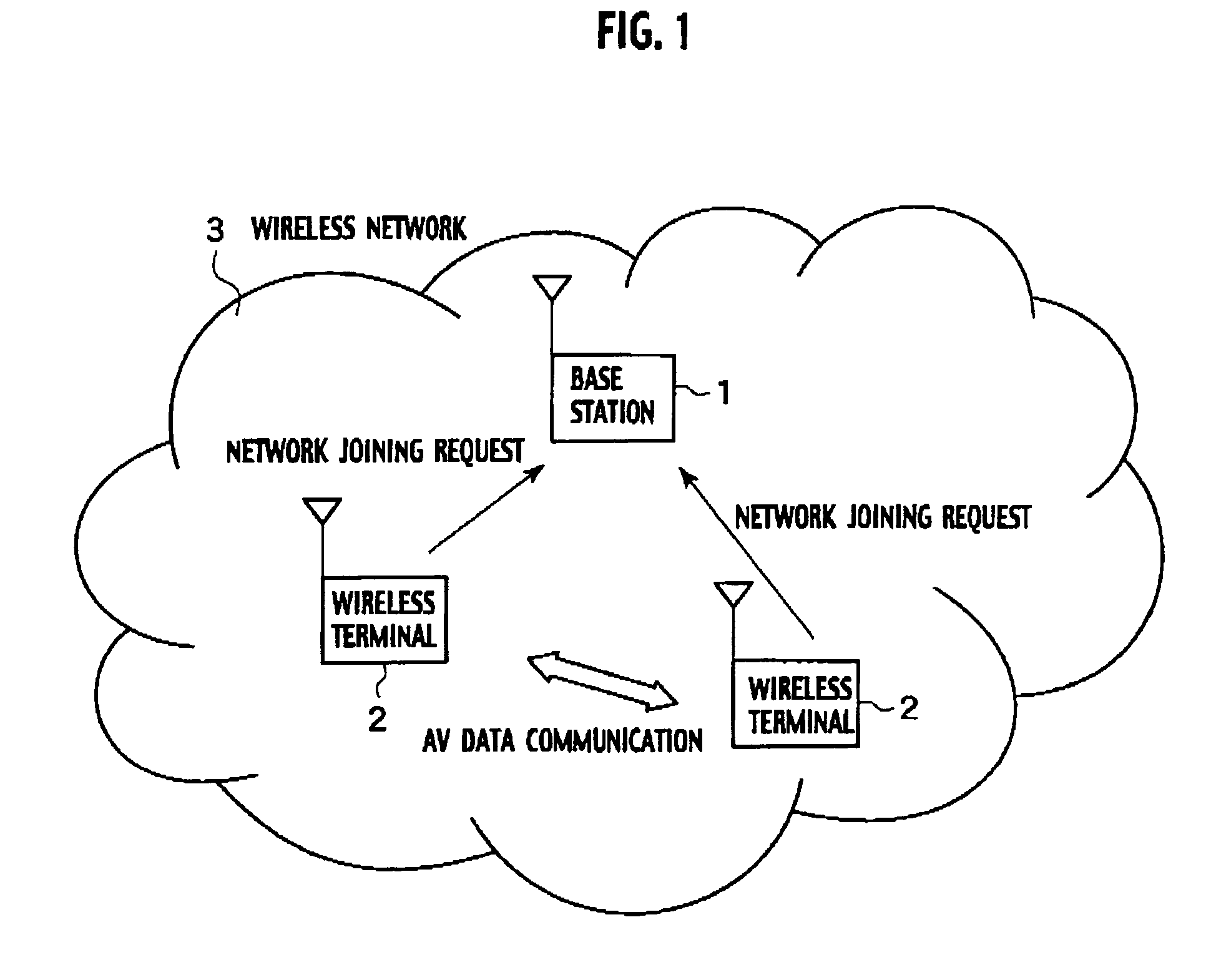
[0077]FIG. 1 shows an exemplary configuration of a wireless network system according to the first embodiment, which comprises a wireless base station (which will be referred hereafter as base station) for managing a wireless network 3, and wireless terminals 2 which join the wireless network 3 after making a joining request to the base station 1 and receiving a permission. In the wireless network of FIG. 1, it is assumed that many wireless terminals can exist besides two wireless terminals shown in the figure.

[0078]Note that the wireless network is not limited to any specific type. For example, it can be a network according to any one of Bluetooth™, IEEE 802.11, HiperLAN2, ARIB wireless 1394™, etc.

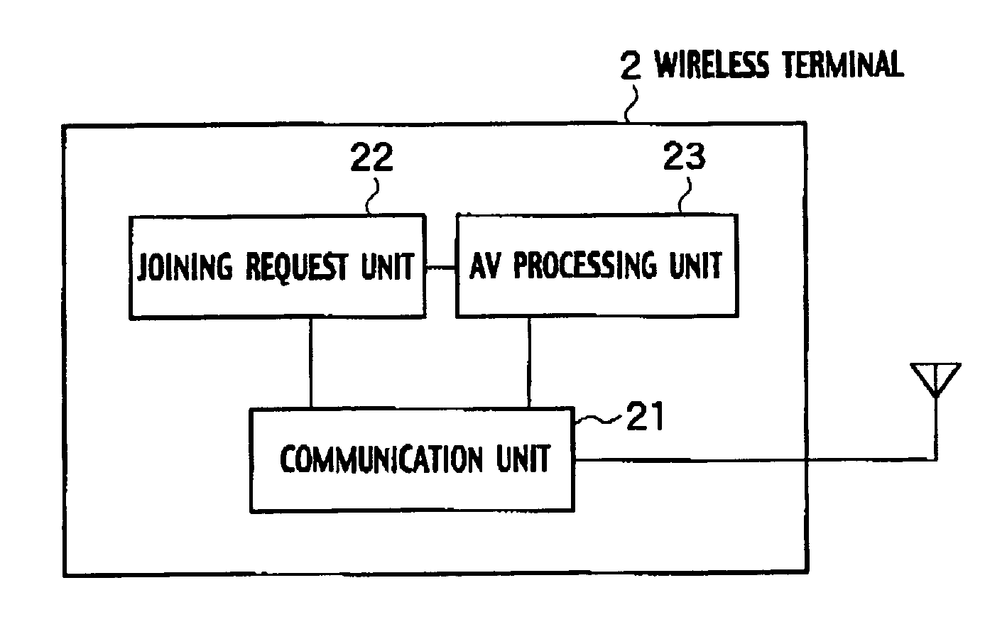
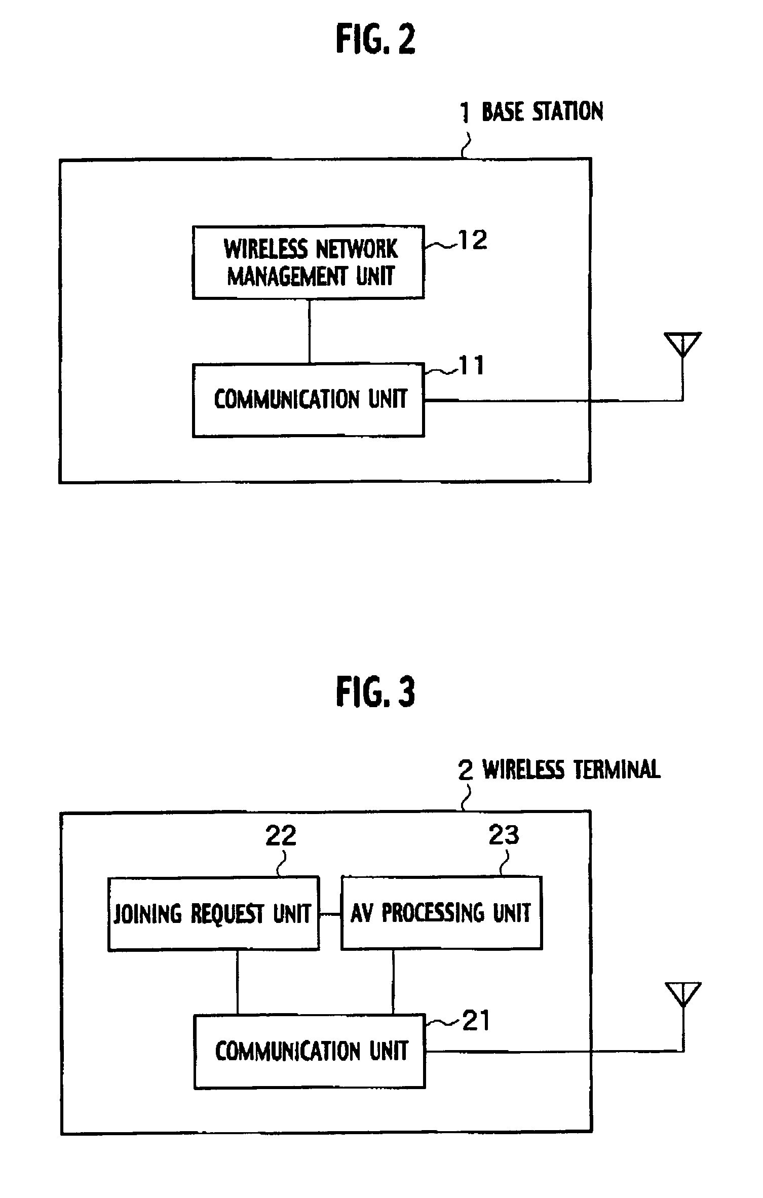
[0079]FIG. 2 shows an exemplary configuration of the base station 1 in this embodiment. As shown in FIG. 2, the base station 1 has a communication unit 11 for carrying out communications with the wi...

second embodiment

[0171]Referring now to FIG. 16 to FIG. 28, the present invention will be described in detail.

[0172]FIG. 16 shows an overall configuration of a wireless communication system according to the second embodiment, that contains a transmitting device, a receiving device and a wireless base station. The wireless communication system of FIG. 16 has a wireless device (referred hereafter as a source device) 101 having a contents reproduction function such as that of a DVD player and a wireless interface for transmitting contents, and a wireless device (referred hereafter as a sink device) 103 for receiving the contents transmitted from the source device 101 through a wireless base station 102. These source device 101, wireless base station 102 and sink device 103 are connected to a local area wireless network A.

[0173]As shown in FIG. 16, another local area wireless network B different from the local area wireless network A is also formed, and a wireless device (referred hereafter as a source ...

third embodiment

[0229]Referring now to FIG. 29 to FIG. 33, the present invention will be described in detail.

[0230]In the second embodiment described above, the source device 101 transmits the contents to the sink device 103 through the wireless base station 102. In contrast, in this third embodiment, the source device 101 transmits the contents directly to the sink device 103, without using the wireless base station.

[0231]In the IEEE 802.11, a communication mode called ad hoc mode in which wireless devices communicate without using the wireless base station is defined. This embodiment is directed to the case of carrying out the communications by utilizing the ad hoc mode, and in the following, the difference from the second embodiment will be mainly described.

[0232]FIG. 29 shows a schematic configuration of the wireless communication system according to the third embodiment of the present invention. As shown in FIG. 29, the source device 101 and the sink devices 303a, 103b and 103c are located wit...


PUM


Abstract

A wireless base station which controls joining of a plurality of wireless terminals to a wireless network, stores a maximum joining possible terminal number which indicates a maximum number of the wireless terminals of each terminal type that can join the wireless network simultaneously, and which is set in advance for each one of a plurality of terminal types that classify the wireless terminals, and a currently joining terminal number which indicates a number of the wireless terminals of each terminal type that are currently joining the wireless network, for each one of the plurality of the terminal types. Then, the wireless base station judges whether the joining of one wireless terminal of one terminal type which sent a request message to the wireless network is permitted or not, according to the maximum joining possible terminal number for the one terminal type and the currently joining terminal number stored for the one terminal type.

Description

BACKGROUND OF THE INVENTION[0001]1. Field of the Invention[0002]The present invention relates to a wireless base station, a network joining control method, a wireless terminal and a communication control method in a wireless network. The present invention also relates to a transmitting device, a receiving device and a wireless base station for transmitting and receiving various types of contents for which the copyright protection is necessary via a network.[0003]2. Description of the Related Art[0004]In recent years, in conjunction with the advance of the LAN (Local Area Network) technique, the networking in the office environment has been developed mainly in forms of wired connections among PCs (Personal Computers).[0005]While such wired LANs are spreading the use of the wireless LAN in which a part of the wired LAN is replaced by radio is also in progress. For example, consider the case where a wireless base station is connected to the wired LAN and a plurality of portable PCs are...

Claims


Application Information

Patent Timeline
Patent Type & Authority Patents(United States)
IPC IPC(8): H04Q7/20G06F15/173H04N7/167H04W12/02H04W12/04H04W12/06H04W28/24H04W48/06
CPCH04L63/0428H04L63/062H04L63/08H04W48/06H04W12/04H04W12/06H04W28/24H04L63/10H04L63/06H04L2463/101H04W84/12H04W12/0471
Inventor NAKAKITA, HIDEAKIISOZAKI, HIROSHITSUNODA, KEIJITOSHIMITSU, KIYOSHISAITO, TAKESHIKATO, TAKU
Owner KK TOSHIBA
Why Eureka
Try Eureka