
Exchange node and exchange node control method

a control method and node technology, applied in the field of exchange node and exchange node control method, can solve the problems of inability to ensure reliability and adequate voice quality, and inability to completely guarantee the quality of real-time communication, etc., to achieve the effect of reducing the delay time in communication, ensuring communication quality, and reducing the delay tim

Inactive Publication Date: 2010-07-20
TOKYO DENKI UNIVERSITY
View PDF13 Cites 32 Cited by
  • Summary
  • Abstract
  • Description
  • Claims
  • Application Information

AI Technical Summary

Benefits of technology

"The present invention aims to solve problems related to communication delay time, traffic congestion, and communication quality in conventional exchange nodes. The invention provides an exchange node that reduces delay time by monitoring output / distribution units, specifying unused time slots for data write, and prioritizing data transfer through priority control signals. The invention also resolves traffic congestion by performing write output to the specified time slot regardless of the communication speed of the transmission path. Additionally, the invention ensures communication quality by using the connection type for the communication method as the delay time in communication can be reduced. Overall, the invention provides an exchange node with improved efficiency and reliability for communication."

Problems solved by technology

Moreover, when accommodating lines of different communication speeds in a mixed manner, an uncertain delay time that cannot be assured is produced depending on the traffic congestion state that occurs when lines of the same communication speed are used in the same period of time thereby inhibiting the enhancement of real-time property.
A priority control that takes the delay time into consideration is possible in the exchange node adopting the ATM method, but it is essentially difficult to completely guarantee the quality of real-time communication when the amount of flow-in traffic differs greatly from the expected value such as fluctuation in delay time or loss of packet when unexpected traffic load flows in since the relevant method assumes that the buffer control is performed in the exchange node.
The UDP does not have the function of re-ordering the order of arrived data to the original order, error restoring function of performing restoration or the like, and thus lacks in reliability and adequate voice quality may not be guaranteed.
In the connection type communication, compliance with respect to the communication quality is possible within a reference range defined in advance in the network, but the connectionless communication must sometimes be used due to problems in that the overhead in communication necessary in call set up control is large and the call set up time until starting the communication is long since it takes a great amount of processing time when occupying the line corresponding to a specific logic channel for communication, the software control on the terminal side and the exchange node side involved in call set up control is complex etc.
However, a technical countermeasure for constantly guaranteeing stable quality in the exchange node is required in the connectionless type communication, and real time communication in which interactive voice, picture information are targets and in which a variety of communication quality (QoS: Quality of Service) and high-quality communication precision or the like are required.
In the Diffserv method, the priority information is given to each IP packet to be transferred by the user so that a relative transfer performance difference is created between a plurality of priority classes, whereby the internet user is able to identify the type of traffic to be transmitted and received without using the signaling procedures, and provide the communication quality corresponding to the relevant type, but the problems related to the delay time in the exchange node are not resolved depending on the communication traffic congestion state even with the Diffserv method.

Method used


Image

  • Exchange node and exchange node control method
  • Exchange node and exchange node control method
  • Exchange node and exchange node control method

Examples


first embodiment

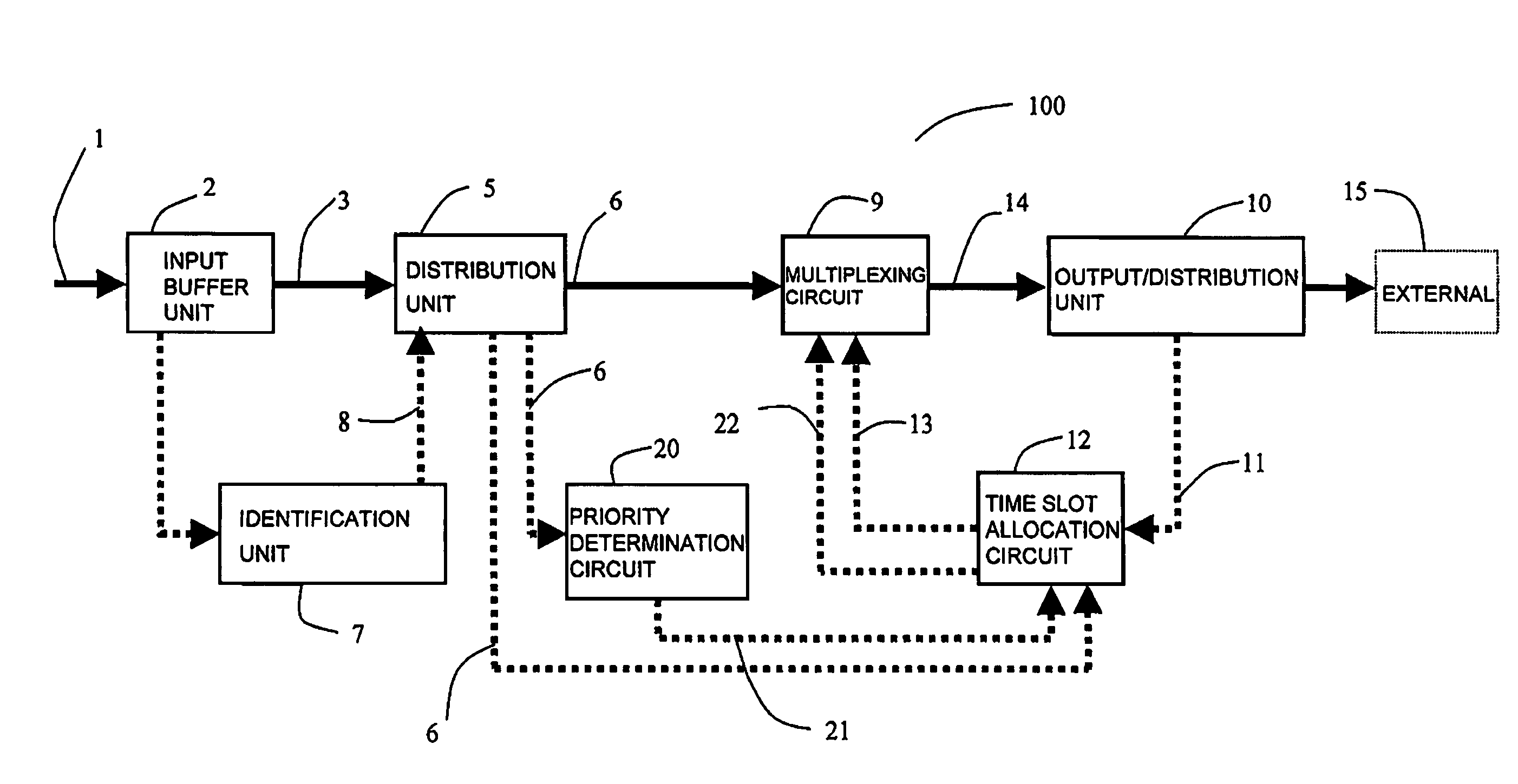
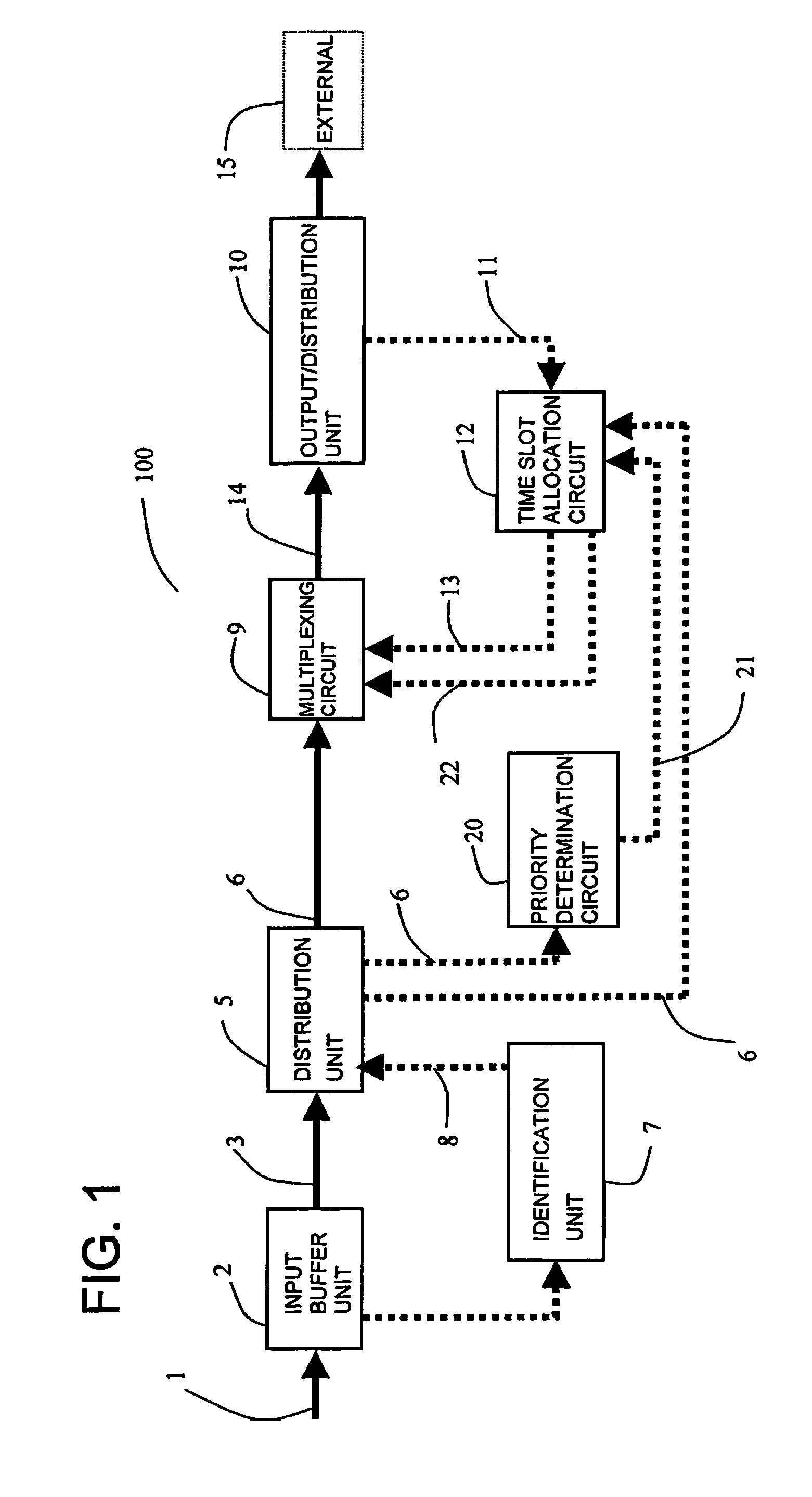
[0467]FIG. 1 is a schematic view showing one form of an exchange node 100 according to the present embodiment. The exchange node 100 includes an input buffer unit 2, an identification unit 7, a distribution unit 5, a multiplexing circuit 9, a time slot allocation circuit 12, and an output / distribution unit 10. More preferably, a frame compression circuit 46 and a frame decompression circuit 18 and a priority judgment circuit 20 described in FIG. 2 are further arranged. The solid line shown in FIG. 1 indicates the flow of main data, and the broken line indicates the flow of control data.

[0468]The input buffer unit 2, connected to a transmission path of the input data 1 which is connection type packet data, writes the input data 1 to a shift register. After the writing of the input data 1 is completed, the input buffer data 3 is output. The exchange node 100 according to the present embodiment performs priority controls when the input data 1 is connection type packet data that contain...

second embodiment

[0485]FIG. 4 is a schematic view showing one form of an exchange node 200 according to the present embodiment. The difference in configuration from the exchange node 100 according to the first embodiment is that a frame compression circuit 16 and a frame decompression circuit 18 are further arranged. The frame compression circuit 16, which is input with the priority control processing data 6 from the distribution unit 5, compresses the time width of the priority control processing data 6 and outputs compressed data 17. The multiplexing circuit 9, which is input with the compressed data 17 as opposed to the priority control processing data 6 of the exchange node 100 according to the first embodiment, outputs the multiplexed data 14 by the time slot specifying signal13 and the “time-series order” of time slot signal 22 from the time slot allocation circuit 12. The frame decompression circuit 18, which is input with the multiplexed data 14 from the multiplexing circuit 9, decompresses ...

third embodiment

[0500]FIG. 29 shows an example of a correspondence relationship of a time slot in one frame of the time division multiplexing line and the direction path on the output side using the exchange node 100 according to the first embodiment or the exchange node 200 according to the second embodiment. In FIG. 29, one example on how each input data (IP data) of different data length transferred with an IP address is specified with the time slot number when a plurality of connections having the same speed for the input side transmission path is established is shown. One frame of the time division multiplexing line in the exchange node is assumed as 125 μsec in FIG. 29. The IP data 1 of 128 bytes and the IP data 2 of 64 bytes are input from the transmission path 1 of 100 Mb / s. The IP data 3 of 64 bytes and the IP data 4 of 128 bytes are input from the transmission path 2 of 100 Mb / s. With regards to the inputs, the time slot allocation circuit 12 specifies two time slots in time of call set-u...


PUM


Abstract

The present invention reduces the delay time to extremely short by monitoring the output / distribution unit of the exchange node to specify the unused time slot as write destination of the data and performing priority control by the priority control signal contained in the data. The traffic congestion is resolved by performing write output to the specified time slot regardless of the communication speed of the transmission path of the data. Furthermore, the present invention aims to provide the exchange node and the exchange node control method that ensures communication quality by using the connection type as the communication method since the delay time in communication can be reduced.The exchange node 100 according to the present invention includes an input buffer unit 2, an identification unit 7, a distribution unit 5, a multiplexing circuit 9, a time slot allocation circuit 12, and an output / distribution unit 10. More preferably, a frame compression circuit 16, a frame decompression circuit 18 and a priority determination circuit 20 are arranged.

Description

CROSS REFERENCE TO PRIOR RELATED APPLICATIONS[0001]This application is a U.S. national phase application under U.S.C. §371 of International Patent Application No. PCT / JP2005 / 017140, filed Sep. 16, 2005, and claims the benefit of Japanese Patent Application No. 2004-300783, filed Oct. 14, 2004, both of which are incorporated by reference herein. The International Application was published in Japanese on Apr. 20, 2006 as International Publication No. WO 2006 / 040903 A1 under PCT Article 21(2).TECHNICAL FIELD[0002]The present invention relates to an exchange node for performing priority control in a connection type packet data communication and a connectionless type packet data communication, and an exchange node control method.BACKGROUND ART[0003]Recently, use of multimedia communication such as image communication, voice communication, high-speed data communication is increasing with widespread use and expansion of the internet, and communication service suited for data communication ...

Claims


Application Information

Patent Timeline
Patent Type & Authority Patents(United States)
IPC IPC(8): H04L12/26H04J3/00H04L12/28H04L47/22H04L47/6275
CPCH04L47/10H04L49/602H04L47/2408H04L47/283H04L47/12H04L12/5601H04L43/0882
Inventor MIYAHO, NORIHARUMIYAHARA, KAZUNORI
Owner TOKYO DENKI UNIVERSITY
Learn More