Supercharge Your Innovation With Domain-Expert AI Agents!

Control system for a failure mode testing system

a control system and testing system technology, applied in the direction of mechanical vibration separation, instruments, counting objects on conveyors, etc., can solve the problems of inability to manually the inability to continuously adjust the various operational parameters, and the inability to achieve continuous adjustment of various operational parameters, so as to facilitate and enhance the testing of products, reduce energy, time and expense, and improve the effect of testing efficiency

Inactive Publication Date: 2006-04-04
NTERA INC
View PDF80 Cites 2 Cited by
  • Summary
  • Abstract
  • Description
  • Claims
  • Application Information

AI Technical Summary

Benefits of technology

The control system enables efficient and accurate adjustment of operational parameters, preventing actuator malfunction and ensuring consistent system performance by dynamically adjusting pressure and frequency, thereby enhancing the reliability and efficiency of failure mode testing.

Problems solved by technology

This difference in frequency causes an interference pattern of the cycling as the actuators come in and out of phase with each other.
Therefore, it is impractical to manually attempt to continuously adjust the various operational parameters that affect actuator operation, such as the pressure and frequency of the cylinders.
Due to the large number of calculations that would have to be performed on a split second basis for each of the six actuators, it is impractical to manually perform the calculations, let alone make the requisite adjustments to the operational parameters of the actuators, without adversely affecting the efficient performance of the testing system.
Additionally, with respect to pressure, it has been observed that by keeping each cylinder at a constant pressure, the actuators have a tendency, due to frictional forces and historesis, to gravitate towards a set point and get stuck, thus causing the actuators to improperly function.
For example, if the pressure is slightly too high, the apparatus will tend to drift up and then get stuck.
Conversely, if the pressure is slightly too low, the apparatus will tend to drift down and then get stuck.
As a result, the apparatus will tend to drift toward the actuator having the lowest energy level, thus causing performance problems.

Method used


Image

  • Control system for a failure mode testing system
  • Control system for a failure mode testing system
  • Control system for a failure mode testing system

Examples


Embodiment Construction

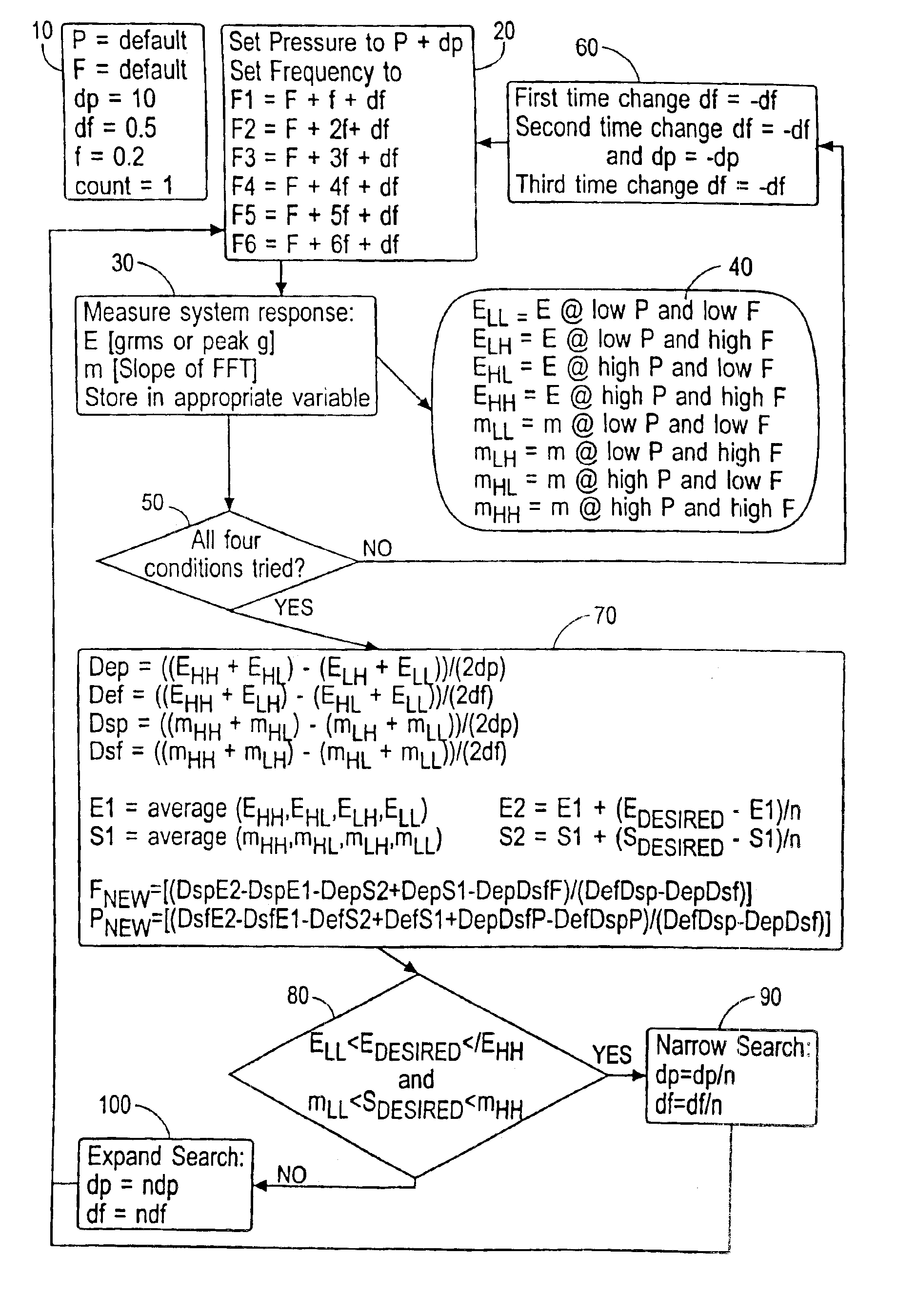
[0032]In accordance with one embodiment of the present invention, a control system employing at least one control algorithm is provided for use in conjunction with a failure mode testing system. The control algorithm enables the testing system to be operated at optimal pressure and frequency levels in order to generate a desired system response. The control algorithm can be incorporated into a computer software program that can be employed to control and operate the failure mode testing system (e.g., a control system).

[0033]The control algorithm of the present invention is actually comprised of a number of discrete algorithms, each of which generally determine a single piece of information, based on data provided by various input sources, such as sensors, detectors, data storage mediums, and so forth.

[0034]By way of a non-limiting example, one set of algorithms determines the change in energy due to pressure, the change in energy due to frequency, the change in slope due to pressure...


PUM

PropertyMeasurementUnit
frequencyaaaaaaaaaa
step frequencyaaaaaaaaaa

Abstract

A control system for a failure mode testing system is described. The control system employs at least one control algorithm that enables the testing system to be operated at optimal pressure and frequency levels in order to generate a desired system response, such as a desired energy level and desired slope of the fast Fourier transform of the system response. Also described are a pressure dither system and a frequency ringing system for enhancing the operation of the actuator cylinders of the failure mode testing system. All three of the systems can be incorporated, either singularly or in combination, into a computer software program that can be employed to operate and control the failure mode testing system.

Description

CROSS-REFERENCE TO RELATED APPLICATIONS[0001]This application is a continuation application of U.S. patent application Ser. No. 10 / 260,037, filed Apr. 17, 2001 U.S. Pat. No. 6,697,746, which is a continuation application of U.S. patent application Ser. No. 09 / 427,456 entitled “Control System For a Failure Mode Testing System, filed Oct. 26, 1999, now U.S. Pat. No. 6,233,530, which is a continuation-in-part application of U.S. patent application Ser. No. 09 / 316,574 entitled “Design Maturity Algorithm”, filed May 21, 1999, now U.S. Pat. No. 6,247,366, which is a continuation-in-part application of U.S. patent application Ser. No. 08 / 929,839 entitled “Method and Apparatus For Optimizing the Design of a Product”, filed Sep. 15, 1997, now U.S. Pat. No. 6,035,715, the entire specifications of which are expressly incorporated herein by reference.FIELD OF THE INVENTION.[0002]The present invention relates to a new and improved control system for a failure mode testing system. The control sys...

Claims


Application Information

Patent Timeline
Patent Type & Authority Patents(United States)
IPC IPC(8): G06M7/06G01M7/02G01M7/04G01M7/06G01M99/00G01N3/02G01N3/32G01N17/00G01N29/04G01N29/12G01N29/46G11B33/14
CPCG01M7/02G11B33/14G01M7/04G01M7/06G01M99/007G01M99/008G01N3/32G01N29/045G01N29/12G01N29/46G01M7/022G01N2203/0202G01N2203/0244G01N2203/0256G01N2291/02827G01N2291/2698
Inventor PORTER, ALEXANDER J.SMITH, MARK ALLEN
Owner NTERA INC
Features
  • R&D
  • Intellectual Property
  • Life Sciences
  • Materials
  • Tech Scout
  • Unparalleled Data Quality
  • Higher Quality Content
  • 60% Fewer Hallucinations
Learn More