
Missile identification and tracking system and method

a missile identification and tracking system technology, applied in the field of identification and tracking of missiles, can solve the problems of not matching the templates, requiring a large number of templates to handle even one target, and becoming difficult to distinguish between a given target that is lofted and another target type that is depressed

Inactive Publication Date: 2006-04-11
LOCKHEED MARTIN CORP
View PDF12 Cites 46 Cited by
  • Summary
  • Abstract
  • Description
  • Claims
  • Application Information

AI Technical Summary

Benefits of technology

[0006]A method according to an aspect of the invention is for tracking a target, which may be a boosting target such as a ballistic missile in its boost phase. The method comprises the steps of sensing information about the target, as for example by means of a radar system or overhead imaging satellite. The information should comprise at least one of (a) target position over time and (b) target positional angle as a function of time relative to the sensor, coupled with sensor position. The information is applied to a plurality of filter sets, where each filter set includes (a) a special filter matched to the parameters of a one predetermined possible type of target and (b) a general filter which is of a more general type. The general filter does not include specifics of possible types of target, and thus the general filter makes no assumptions about the target. The application of the information to each filter set produces, from each of the special and general

Problems solved by technology

The templates are based on the target taking a nominal path, but the target motors may burn long or short, thereby not matching the templates.
When there are very large numbers of templates, there will likely be an overlap between the targets, so that it becomes difficult to distinguish between a given target that is lofted and another target type that is depressed.
For example, a target may have an engine which runs “hot” or “cold,” and it may be directed along a flight path which is either depressed or lofted, thus requiring a very large number of templates to handle even one target.
The large number of variations makes the use of kinematic templates very complex.
In addition, the large number of templates may result in overlap of the kinematic features among various different templates, thereby leading to indeterminate results.

Method used


Image

  • Missile identification and tracking system and method
  • Missile identification and tracking system and method
  • Missile identification and tracking system and method

Examples


Embodiment Construction

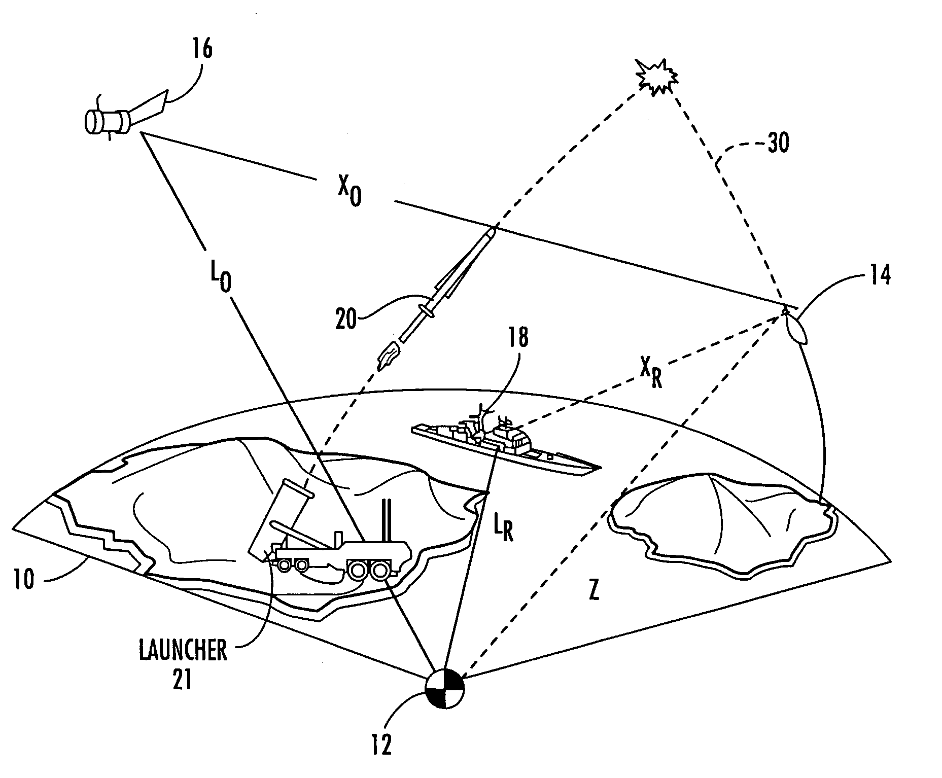
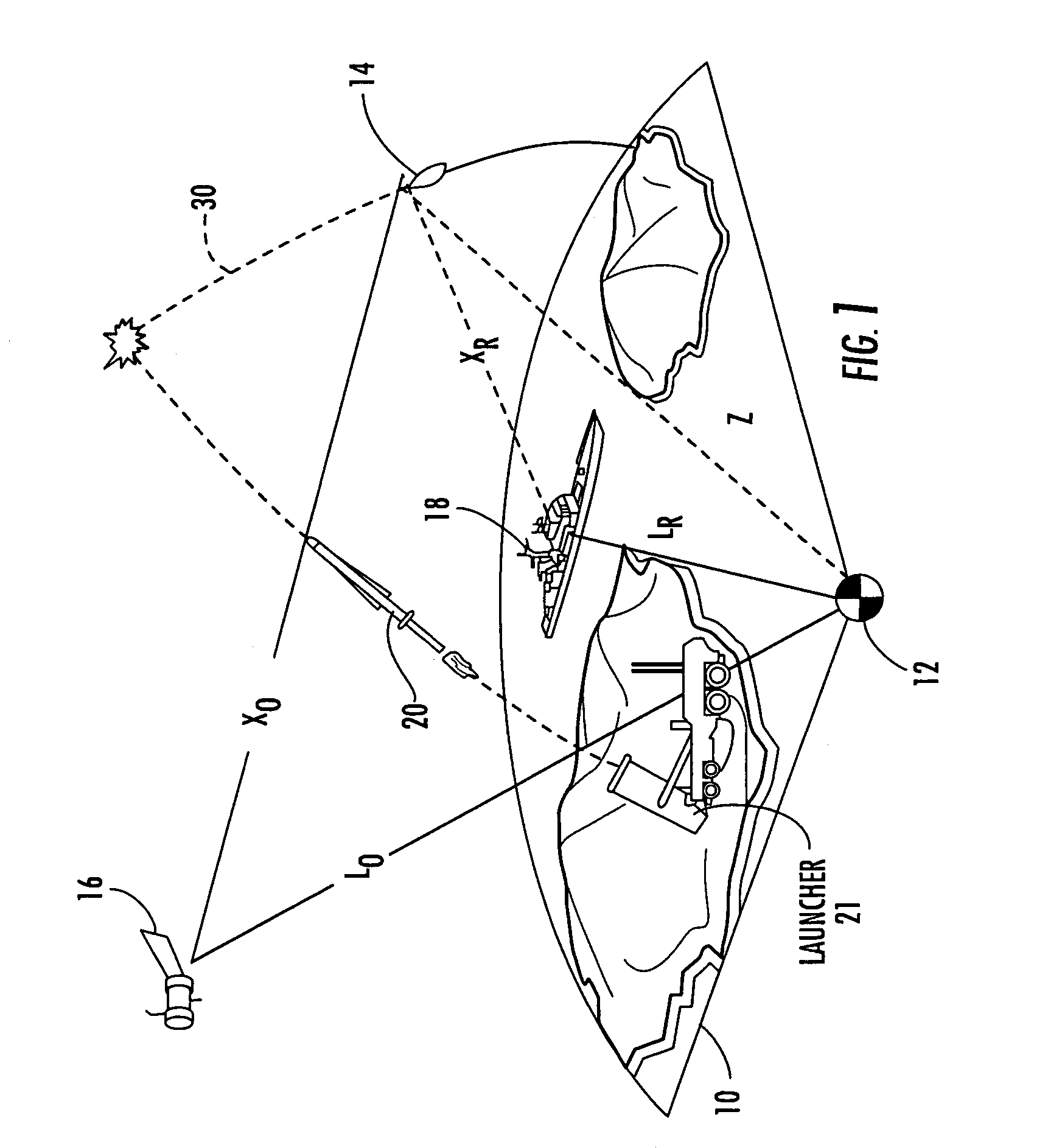
[0010]FIG. 1 is a simplified diagram illustrating the locations relative to Earth 10 and the Earth's center 12 of a target 14, sensing spacecraft 16, shipborne sensing radar 18, and a land-based interceptor 20 using launcher 21 which may use the invention. In FIG. 1, the satellite 16 may include an overhead non-imaging infrared (ONIR) sensor, and X0 represents the distance from ONIR 16 to the target. Distance XR represents the distance from the shipborne radar 18 to the target, distance LR represents the radial distance from the shipborne radar 18 to the Earth's center 12, LO represents the radial distance between the Earth's center 12 and the ONIR spacecraft 16, and distance Z represents the radius between the target 14 and the Earth's center 12.

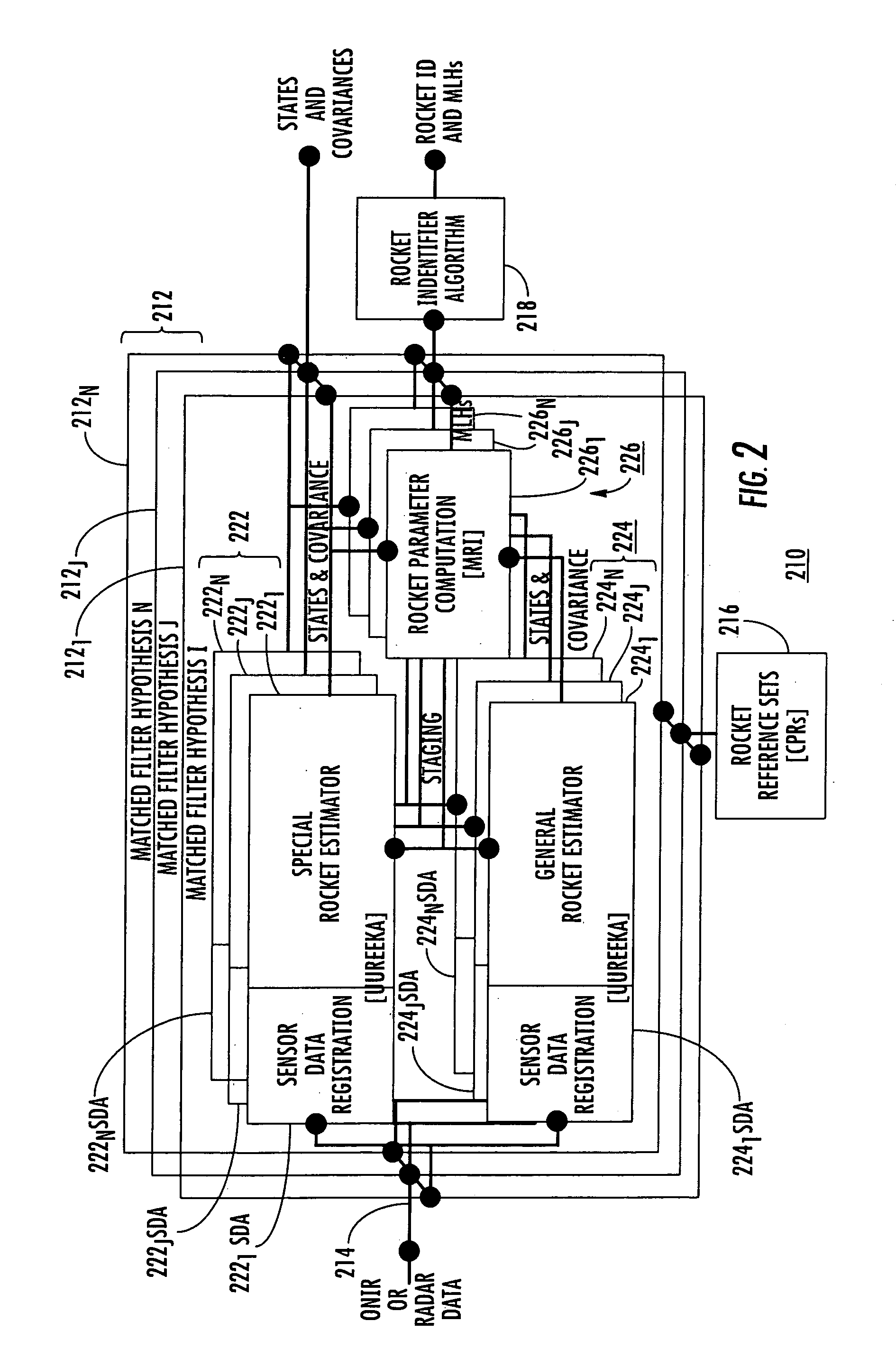
[0011]FIG. 2 is a functional block representation of a Missile Dynamics “Optimal” Tracking System (MDOTS) according to an aspect of the invention. MDOTS taken as a whole incorporates a multi-hypothesis matched filter arrangement that concur...


PUM


Abstract

Sensors determine the kinematic measurements of a boosting missile, and the information is applied to a plurality of pairs or sets of filters, one of which is matched to the characteristics of a particular target type, and the other of which is general, and not matched to a particular target, for producing from each filter of the set missile position, velocity, acceleration, and specific mass flow rate states, and covariances of those states. From the filtered information, the estimates are made of at least missile mass flow rate, thrust, velocity at stage burnout, and remaining burn time. The likelihood is computed that the states and covariances from the filter sets represent the same target. The largest likelihood is selected as representing the target. In one mode, the estimated parameters are weighted and summed for a composite likelihood.

Description

FIELD OF THE INVENTION[0001]This invention relates to the identification and tracking of a missile, especially a missile in its boost phase.BACKGROUND OF THE INVENTION[0002]Tracking and prediction of the future location of missile targets is at the forefront of antiballistic missile defense. Existing methods, such as Interactive Multiple Model (IMM) use multiple hypotheses, and use pattern recognition schemes which compare kinematic information about the target, such as time history of altitude, ground path, and flight angle versus time, with a template. This prior art requires large numbers of templates, as for each target there are altitude, flight path, ground path. The templates are based on the target taking a nominal path, but the target motors may burn long or short, thereby not matching the templates. The enemy may change any of the parameters of the flight path, such as lofting or depressing the flight path, so as to avoid matching a template. A template technique, to be ef...

Claims


Application Information

Patent Timeline
IPC IPC(8): G01S13/72
CPCG01S13/723G01S7/415
Inventor MAVROUDAKIS, PETER J.BOKA, JEFFREY B.PATEL, NARESH R.
Owner LOCKHEED MARTIN CORP
Learn More