Methods and apparatus for shaping antenna beam patterns of phased array antennas

a phased array antenna and beam pattern technology, applied in the direction of antennas, electrical equipment, radio transmission, etc., can solve the problems of reducing the array gain and, therefore, the transmitted and received power levels, and no other method than some form of tapering has been used for these purposes, so as to reduce the sidelobe level reduce the width of the main lobe of the antenna beam pattern, and increase the power of the main lob

Active Publication Date: 2006-04-11
HARRIS CORP
View PDF8 Cites 34 Cited by
  • Summary
  • Abstract
  • Description
  • Claims
  • Application Information

AI Technical Summary

Benefits of technology

[0012]In addition to the phase and amplitude distribution resulting from the radiation shaping transformation, the antenna element control module can apply amplitude tapering to the phased array antenna to reduce sidelobe levels of the antenna radiation pattern relative to a uniform illumination radia

Problems solved by technology

To date, no methods other than some form of tapering have been in use for these purposes.
The resultant tradeoff for reduction in sidelobe levels by means of tapering is an

Method used


Image

  • Methods and apparatus for shaping antenna beam patterns of phased array antennas
  • Methods and apparatus for shaping antenna beam patterns of phased array antennas
  • Methods and apparatus for shaping antenna beam patterns of phased array antennas

Examples


Embodiment Construction

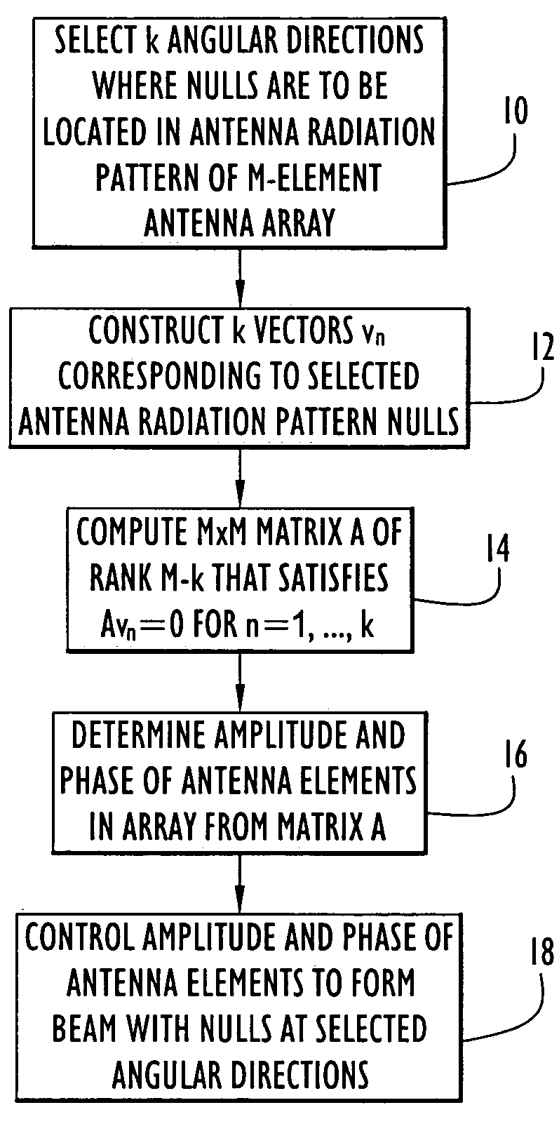
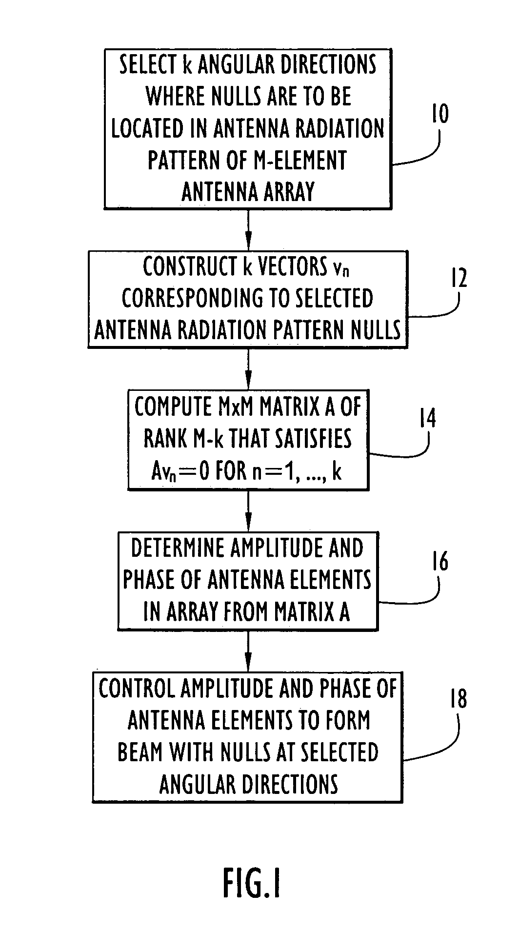
[0024]The following detailed explanations of FIGS. 1–10 and of the preferred embodiments reveal the methods and apparatus of the present invention. A new scheme for flexible shaping of radiation patterns is presented, with a wide range of possible applications. These include, but are not restricted to, array sidelobe reduction. For this application, improvement over existing conventional amplitude-tapering methods can be achieved in which greater reduction in sidelobe levels is achieved while maintaining main lobe widths less than or at most equal to those yielded by tapering methods alone.

[0025]As used herein, the terms antenna beam(s), or simply “beam(s)”, refer generally to transmitted energy concentrated in a certain direction or a sensitivity or receptiveness of the antenna to signals arriving from particular directions. The antenna beam is formed by a directional antenna and is directed over a particular angular region in accordance with the antenna pattern (i.e., the radiated...


PUM


Abstract

A method of forming an antenna beam with a phased array antenna having an array of antenna elements includes selecting angular directions at which nulls are to be located in an antenna radiation pattern of the phased array antenna, computing a radiation shaping transformation as a function of the selected angular directions, and determining from the radiation shaping transformation an amplitude and phase distribution over the array of antenna elements that forms the antenna beam with nulls of the antenna radiation pattern at the selected angular directions. Computing of the radiation shaping transformation involves constructing a set of vectors corresponding to the selected antenna radiation pattern nulls, and computing a matrix whose product with each of the vectors is zero. The amplitude and phase distribution is determined from the matrix.

Description

BACKGROUND OF THE INVENTION[0001]1. Field of the Invention[0002]The present invention relates to beamforming techniques for phased array antennas and, more particularly, to methods and apparatus for shaping antenna beam patterns.[0003]2. Description of the Related Art[0004]Phased array antennas are used in a wide variety of applications to transmit and receive directed beams of electromagnetic energy. The shape and direction of the antenna beam produced by such antennas are determined by the relative phases and amplitudes of the signals at the individual antenna elements that constitute the phased array. For example, where hardware permits the relative phases of the antenna elements to be adjusted during operation, the main lobe of the antenna radiation pattern can be steered over a range of different directions to transmit a signal in a selected direction or to receive a signal arriving from a particular direction.[0005]It is customary to employ non-uniform illumination, sometimes ...

Claims


Application Information

Patent Timeline
IPC IPC(8): H01Q3/00H01Q3/26
CPCH01Q3/36H01Q3/28H01Q3/2611H04B7/0617
Inventor MINKOFF, JOHNCANGIANI, GENE L.
Owner HARRIS CORP
Why Eureka
Try Eureka