Display device having flexibility and a winding axis that winds the two slidable plates

a technology of sliding plate and display device, which is applied in the direction of identification means, instruments, non-linear optics, etc., to achieve the effect of simple configuration

Inactive Publication Date: 2006-04-11
KK TOSHIBA
View PDF6 Cites 61 Cited by
  • Summary
  • Abstract
  • Description
  • Claims
  • Application Information

AI Technical Summary

Benefits of technology

[0009]In view of the above-mentioned problem, an object of the present invention is to provide a flexible display device with a simple configuration.
[0018]a second close contact member which has flexibility and which is provided linearly in the second direction within a surface of the second thin plate which faces the first thin plate, the first thin plate and the second thin plate being slidably engaged with each other.

Problems solved by technology

However, the above-described display devices have a problem that they have complicated structures, and therefore a bendable display device with a simple configuration has been desired.

Method used


Image

  • Display device having flexibility and a winding axis that winds the two slidable plates
  • Display device having flexibility and a winding axis that winds the two slidable plates
  • Display device having flexibility and a winding axis that winds the two slidable plates

Examples


first embodiment

[0062][First Embodiment]

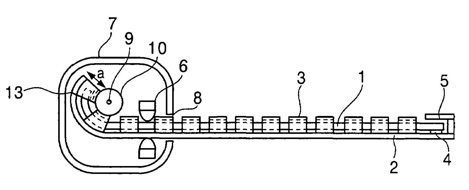
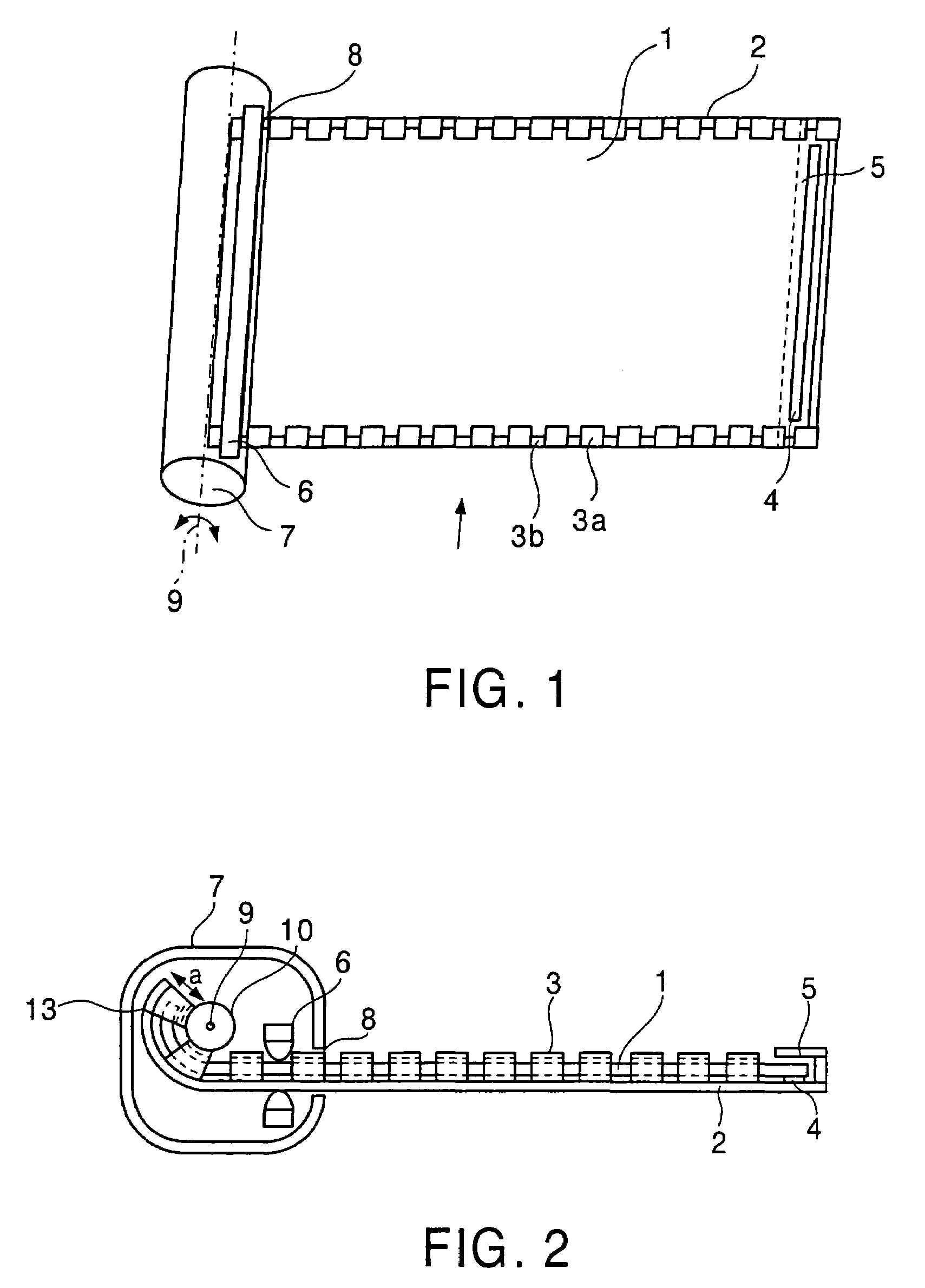
[0063]First, a first embodiment of the present invention is described. FIG. 1 is an oblique perspective view showing an active matrix type display device of this embodiment, and FIG. 2 is a perspective view as seen from a direction of an arrow in FIG. 1.

[0064]As shown in FIG. 1 and FIG. 2, the active matrix type display device of this embodiment has a display part in which a liquid crystal cell (a first thin plate) 1 which will be a display main part and a backlight (a second thin plate) 2 which will be a display secondary part are stacked one upon the other. In this embodiment, the surface on the liquid crystal cell 1 side becomes a display surface.

[0065]The liquid crystal cell 1 and backlight 2 are integrated by a plurality of retainers (guide members) 3a which are provided on two parallel sides of the backlight 2 and which partially cover surface end portions of the surface of the liquid crystal cell 1 on the side not facing the backlight 2. Specifically, ...

second embodiment

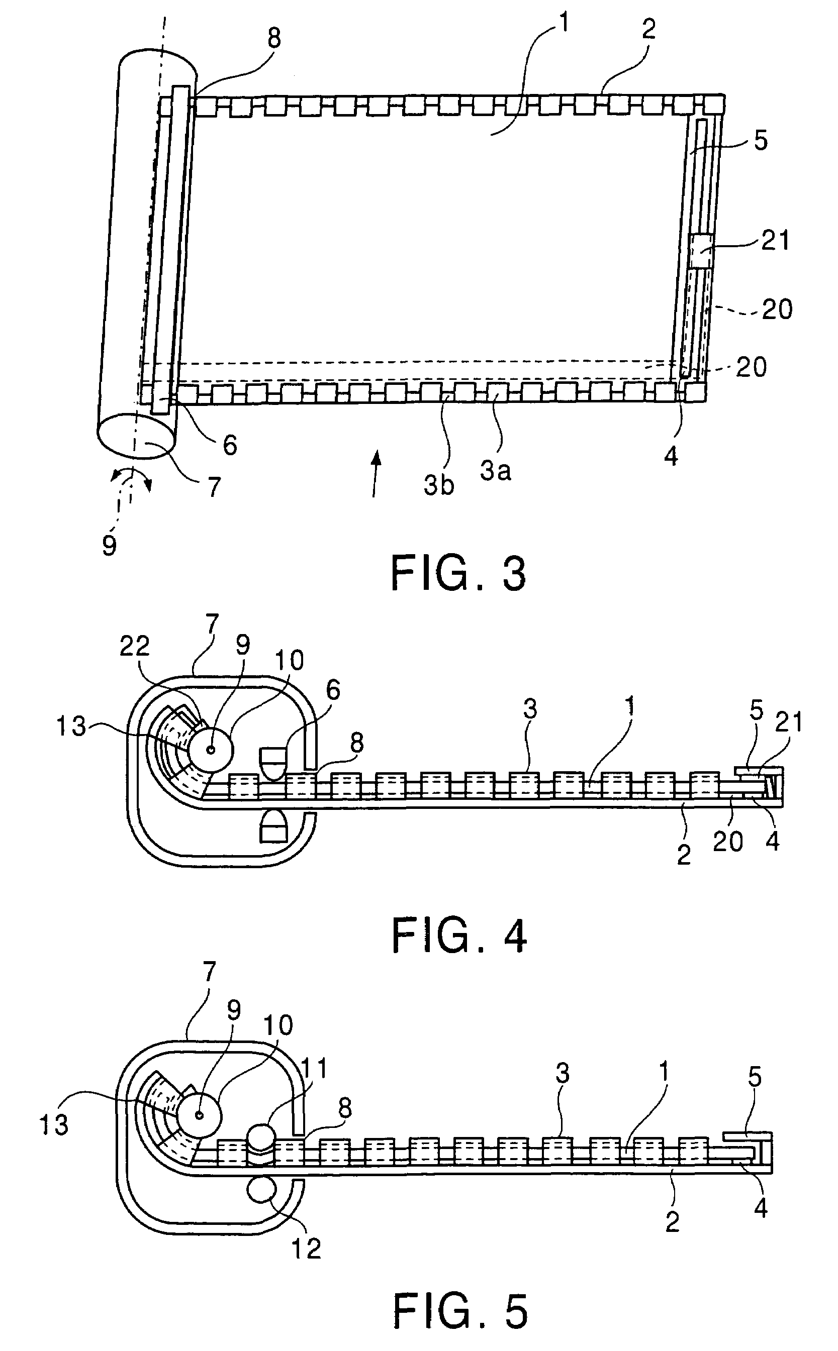
[0092][Second Embodiment]

[0093]Next, a second embodiment is described using FIG. 5. FIG. 5 is an oblique perspective view showing an active matrix type display device of this embodiment. This embodiment is described regarding points different from the first embodiment, and the descriptions of the same portions are omitted.

[0094]The active matrix type display device of this embodiment is different from that of the first embodiment in that a first rotator 11 and a second rotator 12 are provided as shown in FIG. 5 in place of the clamps 6 in FIG. 1. These rotators 11 and 12 are provided linearly and parallel to a winding axis 9, the first rotator 11 being provided in contact with a liquid crystal cell 1 and the second rotator 12 being provided in contact with a backlight 2.

[0095]When a display part in which the liquid crystal cell 1 and backlight 2 are integrated is wound in or drawn out, these rotators 11 and 12 can hold the display part therebetween and apply forces to send the displ...

third embodiment

[0101][Third Embodiment]

[0102]Next, a third embodiment is described using FIGS. 7A and 7B. FIG. 7A is a plane view showing an active matrix type display device according to this embodiment, and FIG. 7B is a side view as seen from a direction of an arrow in FIG. 7A. Further, in this embodiment, a manufacturing process of a retainer 3 described in the first embodiment is also explained using FIGS. 8A and 8B. FIG. 8A is a plane view showing a manufacturing method of a retainer of the active matrix type display device of this embodiment, and FIG. 8B is a side view as seen from a direction of an arrow in FIG. 8A. As for FIGS. 7A and 7B and FIGS. 8A and 8B, although the illustration and description regarding an accommodating container 7 including a roller 10 are omitted, the left side is the winding axis end and the right side is the display part drawn end in these drawings. This embodiment is described regarding points different from the first embodiment, and the descriptions of the same...


PUM

PropertyMeasurementUnit
thicknessaaaaaaaaaa
thicknessaaaaaaaaaa
thicknessaaaaaaaaaa

Abstract

A display device disclosed herein comprises: a display part including a first thin plate having flexibility and a second thin plate having flexibility, the second thin plate being provided on the first thin plate; a fixing portion which fixes the first thin plate and the second thin plate together on a first direction within each main surface of the first and second thin plates; and a close contact member which is provided in a second direction perpendicular to the first direction within the main surface, and which brings the first thin plate and the second thin plate into close contact.

Description

CROSS-REFERENCE TO RELATED APPLICATIONS[0001]This application is based upon and claims the benefit of priority from the prior Japanese Patent Application No. 2003-072999, filed on Mar. 18, 2003, the entire contents of which are incorporated herein by reference.BACKGROUND OF THE INVENTION[0002]1. Field of the Invention[0003]The present invention relates to a display device, and more particularly to a display device having flexibility.[0004]2. Related Background Art[0005]Active matrix type display devices in which active elements such as TFTs are arranged at pixels can realize flat type display devices with high image quality. As display parts of the active matrix type display devices, liquid crystal being a light shutter, organic EL which emits light, and electrophoretic devices (enclosed in microcapsules or not), can be used. These active matrix type display devices, having a thin profile and lightweight, are therefore most suitable for display devices of portable information equipm...

Claims


Application Information

Patent Timeline
Patent Type & Authority Patents(United States)
IPC IPC(8): G02F1/1333G02F1/13357G09F9/00G09F9/30H01L51/50
CPCG09F9/30G02F1/133305A47J19/027A47J19/06A47J43/07
Inventor AKIYAMA, MASAHIKOTANAKA, MASAOHARA, YUJIROFUKUSHIMA, RIEKO
Owner KK TOSHIBA
Why Eureka
Try Eureka