Fiber optic switch employing optical amplifiers

a fiber optic switch and amplifier technology, applied in the field of fiber optic switch employing optical amplifiers, can solve the problems of not working well for switching broadband signals, relying on nonlinearities, and slow switching speed of most of these switching methods

Inactive Publication Date: 2006-04-11
THE UNITED STATES OF AMERICA AS REPRESENTED BY THE SECRETARY OF THE NAVY
View PDF4 Cites 54 Cited by
  • Summary
  • Abstract
  • Description
  • Claims
  • Application Information

AI Technical Summary

Problems solved by technology

As a result of requiring a change in the propagating medium to achieve switching, most of these switching methods have relatively slow switching speeds, e.g., on the order of 100 Hz.
These methods typically rely on nonlinearities.
The problem with a nonlinear system is that it does not work well for switching broadband signals, which can be viewed as sums of narrowband signals.
What is needed is a methodology for switching an optical input signal into a plurality of optical outputs that does not depend upon nonlinearities or upon the implementation of a change in medium giving rise to unacceptably slow switching speeds.

Method used


Image

  • Fiber optic switch employing optical amplifiers
  • Fiber optic switch employing optical amplifiers
  • Fiber optic switch employing optical amplifiers

Examples


Embodiment Construction

)

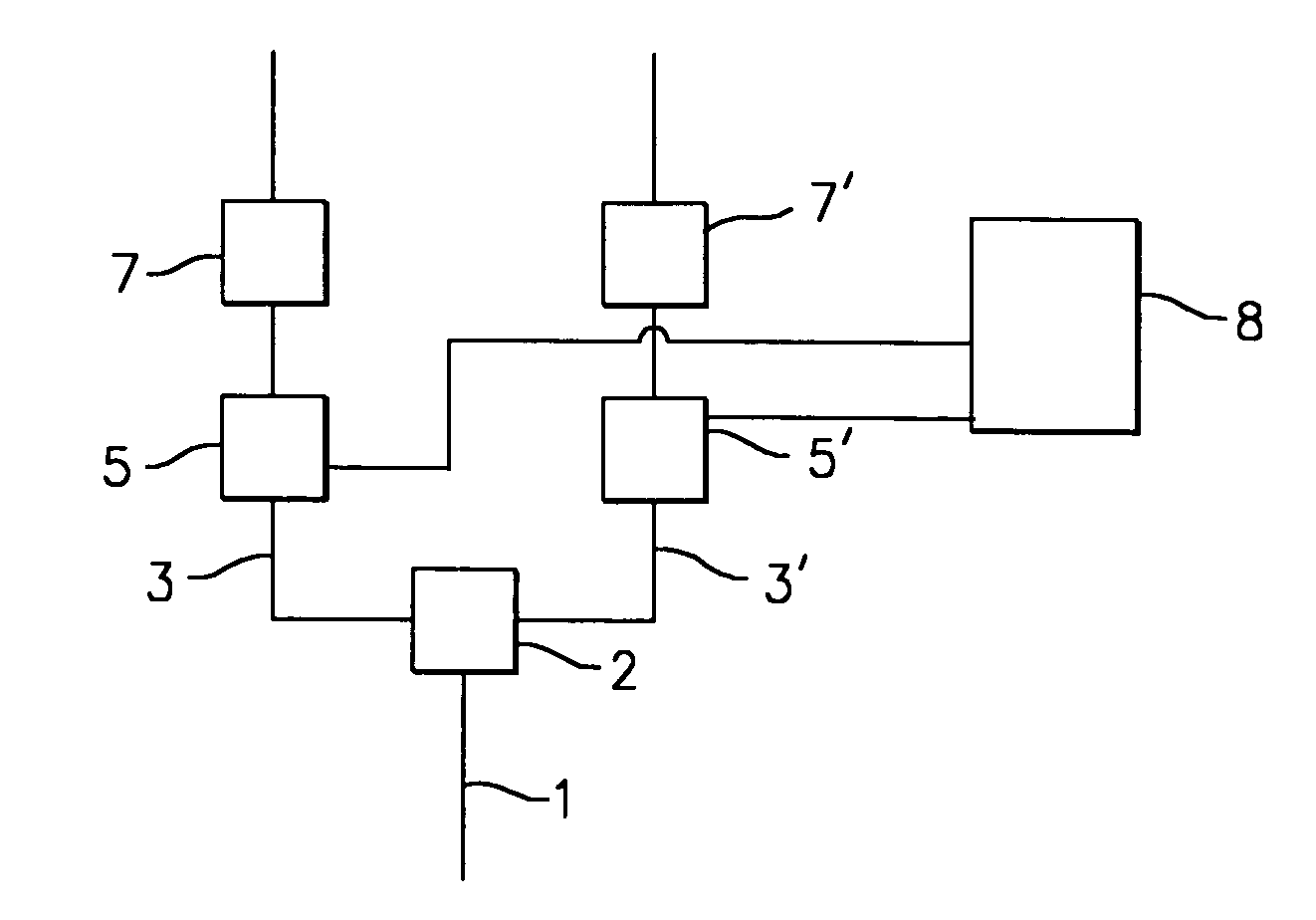
[0016]The optical switch of the present invention switches a digital signal from an input optical fiber to one or more output optical fibers. The embodiments of the present invention, discussed more fully below, function in a fiber optic system using two discrete power states for “0” and “1”. Switching is achieved by splitting an optical input signal into a plurality of signals, selectively amplifying certain of the split signals through a controller, and then attenuating all of the split signals to provide at least one output signal corresponding to the optical input signal.

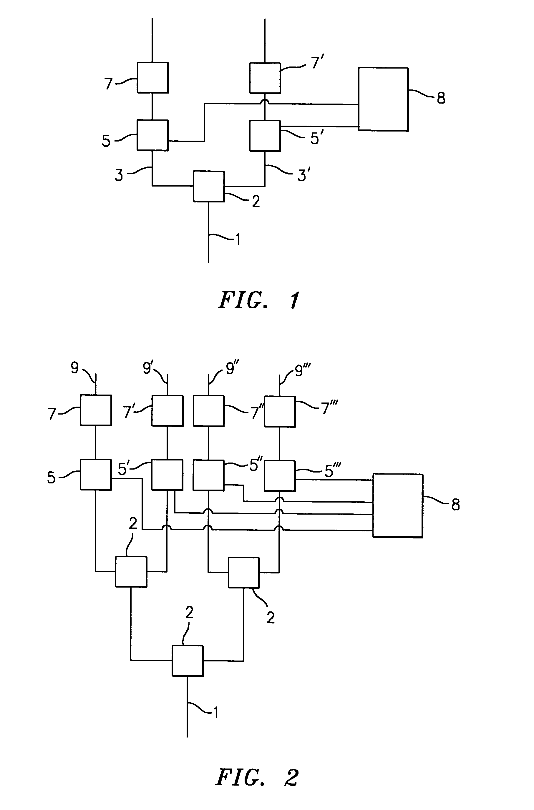
[0017]With reference to FIG. 1, there is illustrated an embodiment of an optical switch of the present invention. The incoming signal to be switched is contained by fiber 1. The signal is split into two fibers 3, 3′ with a splitter 2. Splitter 2 is a device well known in the art that divides a single incoming optical signal into at least two separate output signals such that each output signal corresponds to th...


PUM


Abstract

A method and apparatus of switching a digital signal from a single input optical fiber to one or more optical fibers comprising the steps of providing an input signal into the input optical fiber, splitting the input optical fiber to form a plurality of split optical fibers each carrying the input signal, amplifying the signal in at least one of the plurality of split optical fibers with a laser activated amplifier, and then attenuating the signal in all of the split optical fibers to produce at least one output signal in one or more of the designated split optical fibers.

Description

STATEMENT OF GOVERNMENT INTEREST[0001]The invention described herein may be manufactured and used by or for the Government of the United States of America for governmental purposes without the payment of any royalties thereon or therefore.CROSS REFERENCE TO OTHER PATENT APPLICATIONS[0002]This patent application is co-pending with a related patent application Ser. No. 10 / 748,921 also entitled A FIBER OPTIC SWITCH, by Anthony A. Ruffa the named inventor of this application.BACKGROUND OF THE PRESENT INVENTION[0003](1) Field of the Invention[0004]The present invention relates to a method for switching a digital signal in an optical fiber from an input fiber to a plurality of output fibers and an apparatus for performing such switching. More specifically, the present invention relates to a method for switching a digital signal in an optical fiber from an input fiber to a plurality of output fibers by means of at least one laser-activated amplifier and a plurality of optical attenuators w...

Claims


Application Information

Patent Timeline
Patent Type & Authority Patents(United States)
IPC IPC(8): H01S3/00G02B6/42
CPCH01S3/06754
Inventor RUFFA, ANTHONY A.
Owner THE UNITED STATES OF AMERICA AS REPRESENTED BY THE SECRETARY OF THE NAVY
Why Eureka
Try Eureka