Range adaptable system for determining the angular position and distance of a radiating point source and method of employing

Active Publication Date: 2006-04-11
NORTHERN DIGITAL
View PDF3 Cites 98 Cited by
  • Summary
  • Abstract
  • Description
  • Claims
  • Application Information

AI Technical Summary

Benefits of technology

[0015](6) One example of an application uses a 4,096 element CCD array with a mask pattern containing four frequencies, including the fundamental frequency f0 with period of 4,096 pixels, f1=4*f0, f2=16*f0, and f3=64*f0. The mask length (˜8192 pixels) is longer than the detector to ensure that the detector is fully covered by the pattern for all source positions. The phase determination of each of the spectral peaks allows resolving to finer and finer degrees as with a vernier caliper.

Problems solved by technology

(1) The present invention is disclosed in terms of two preferred embodiments. In each of these embodiments, a patterned mask or coded aperture is located at a distance from a linear array comprising a detector surface. The mask pattern consists of a transmissivity pattern varying in one dimension, e.g., in the Y-axis. In each of the embodiments, a point radiating source illuminates the aperture to cast an image onto the array. Computing means is employed to identify one or more frequencies in the frequency domain to determine the image scale and shift along the detector array axis.
(2) In further amplification of the BACKGROUND OF THE INVENTION, the main distinction between the embodiments of the present invention and the prior art is that, in the present invention, a method of determination is employed that automatically allows determination of the magnification of the aperture image, with this method employing frequency domain techniques. The prior art fails to teach or suggest a way to account for image magnification that occurs due to the proximity of the source and the detector. Through the use of the techniques disclosed herein, the aperture pattern is automatically re-scaled to match that of the actual image, so that an accurate determination of pattern shift can be made.
(3) A first embodiment of the present invention has two variations, one of which employs the use of multiple single frequency components and phase methodology, the second of which uses multiple single frequency components as well as a variable frequency component, all of which are identified in “frequency domain.” The particular locations of frequency components as well as the corresponding phases of single frequency components allow the determination of the magnified image shift on the detector axis. The flowchart of FIG. 16 depicts these variations.

Method used


Image

  • Range adaptable system for determining the angular position and distance of a radiating point source and method of employing
  • Range adaptable system for determining the angular position and distance of a radiating point source and method of employing
  • Range adaptable system for determining the angular position and distance of a radiating point source and method of employing

Examples


first embodiment

[0062]A variation in the first embodiment uses an additional component to the mask pattern, which is a sinusoid with spatially varying frequency. A preferred spatial dependency is linear dependence. The FFT of the image received by the detector array allows determination of the centroid of the varying frequency component and from this information, the approximate pattern position and corresponding angle of incidence are known. From this approximate solution, the phases of the single frequency components can be determined in sequence as explained above. The advantage and novelty of this variation is that the mask can be made much larger than the fundamental period of one array length. This also allows for the mask to be kept at a much greater distance from the detector surface, increasing the angular sensitivity and the ability to manufacture the device.

[0063]The following equation expresses the mask transmissivity function:

[0064]Mask1:=0.5+[cos⁡(i·1001024·2·π)+cos⁡(i·201024·2·π)+cos...

second embodiment

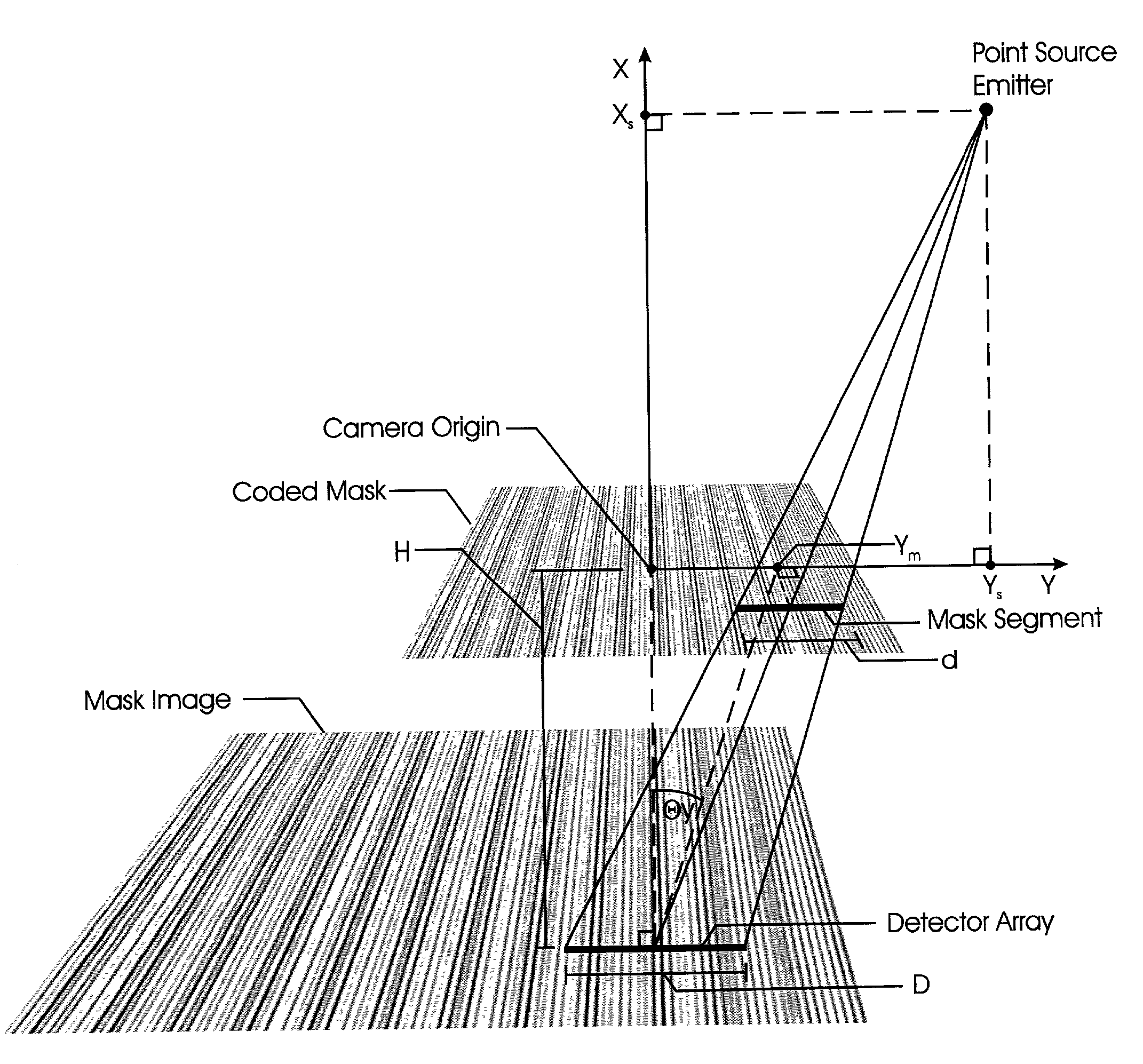
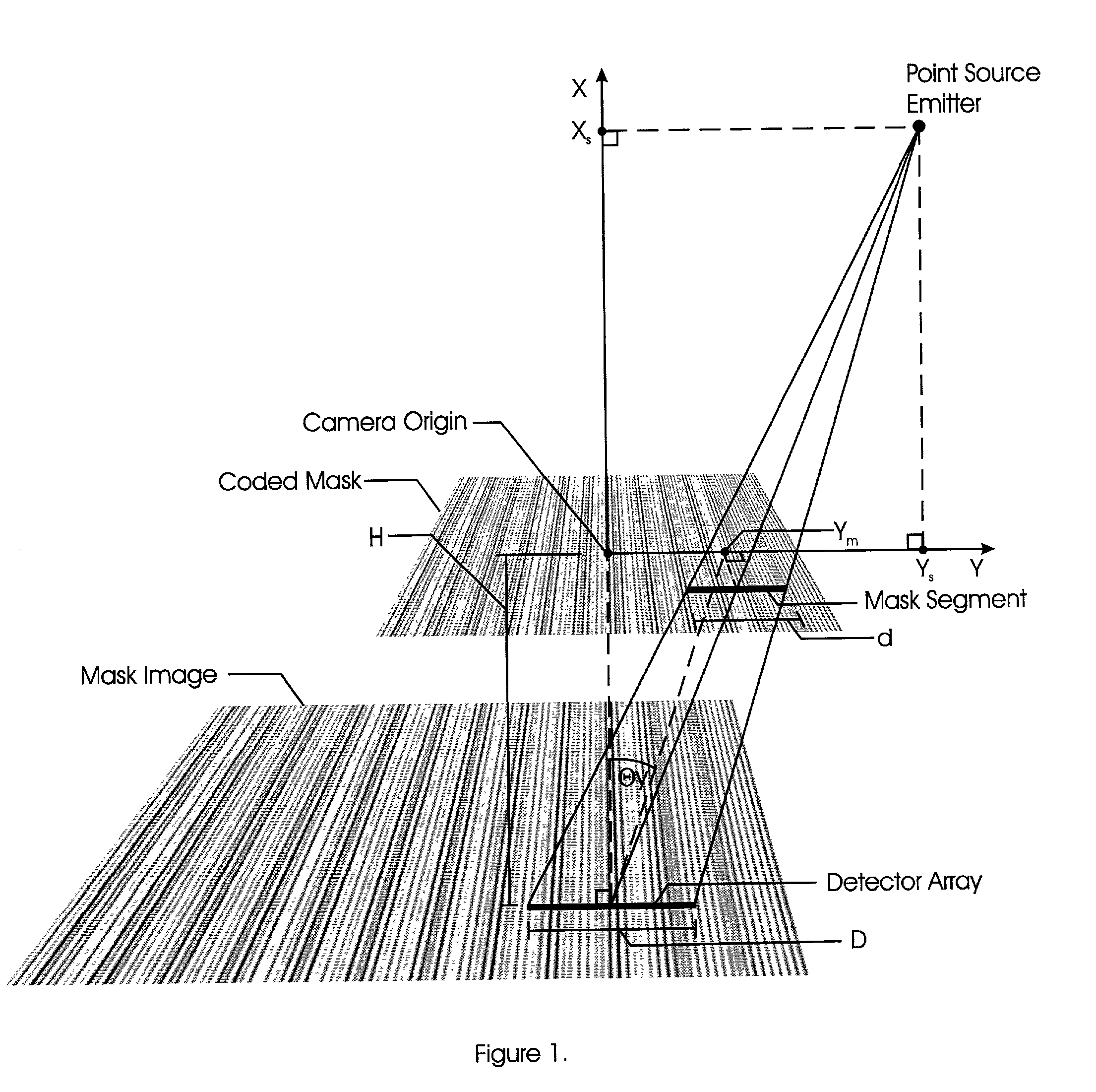
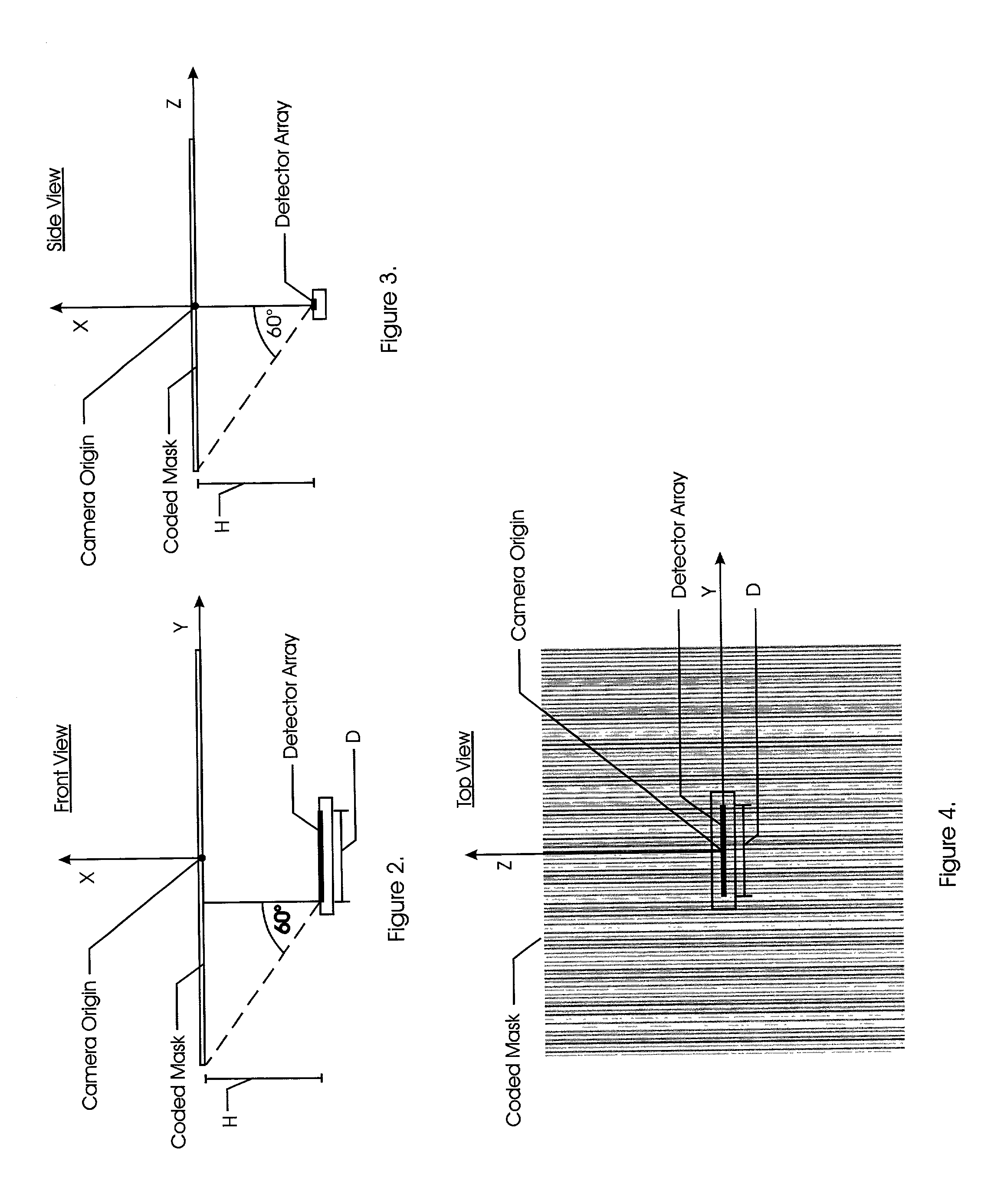
[0072]the present invention describes a method for determining the angular position of a point source of radiation with respect to a detector by examining the scales and shifts of periodic components of the projected image of a variable transmissivity mask. This embodiment uses the system depicted in FIGS. 1–4 and encodes the transmissivity mask with a single frequency component and a broadband component and computes the frequency spectrum of the received detector pattern. The single frequency component (fm) is generally chosen to be near the maximum frequency recordable by the imaging device and / or the maximum frequency within the diffraction limit, so that the best magnification resolution may be obtained. The broadband function used for correlation (fcorr) may be represented by a closed form function such as a polynomial or trigonometric function or it may be a numerical function, such as a pseudo-random sequence or universal redundant array. Ideally, the function will have a nea...


PUM

PropertyMeasurementUnit
distanceaaaaaaaaaa
distanceaaaaaaaaaa
distanceaaaaaaaaaa

Abstract

A patterned mask is located at a distance from a linear detector array. A point radiating source illuminates the aperture to cast an image onto the array. A computer is employed to identify frequencies in the frequency domain to determine the image scale and shift along the detector array axis. Determination of the magnification of the aperture image is made employing frequency domain techniques, the aperture pattern being re-scaled to match that of the actual image, so that determination of pattern shift can be made. A first embodiment of the present invention has two variations, one of which employs the use of multiple single frequency components and phase methodology, the second of which uses multiple single frequency components as well as a variable frequency component. In a second embodiment, a composite image is also used except that only one single frequency component is used in addition to a non-periodic function.

Description

BACKGROUND OF THE INVENTION[0001]The present invention relates to methods of employing a range adaptable system for determining the angular position and distance of a radiating point source as well as the system itself. In the present invention, radiation from a point source travels through a window mask pattern and onto the surface of a sensor. In the prior art, this general concept is well known, however, the prior art fails to teach or suggest the specific techniques employed by Applicant to accurately measure angular position and distance using such a structure.[0002]Prior art systems have used masked or coded apertures placed above multi-element detectors. All of these techniques have attempted to determine the position of a projected pattern on a detector surface by comparing signals from fixed detector elements arranged in a unique pattern or from comparison to fixed reference signals previously stored in a computer. Such techniques result in limited resolution due to the fac...

Claims


Application Information

Patent Timeline
Patent Type & Authority Patents(United States)
IPC IPC(8): G06K9/00G01N21/00G01B11/26G01S3/783G01S5/16G01S11/12
CPCG01B11/26G01S3/7835G01S11/12G01S5/16
Inventor ODELL, DON
Owner NORTHERN DIGITAL
Why Eureka
Try Eureka