
Enhanced system for yaw stability control system to include roll stability control function

a technology of stability control and function, which is applied in the direction of non-deflectible wheel steering, underwater vessels, braking components, etc., can solve the problems of not being able to direct measure, the standard yaw stability control system will not directly or automatically improve the stability of vehicular roll

Inactive Publication Date: 2006-04-11
FORD GLOBAL TECH LLC
View PDF161 Cites 16 Cited by
  • Summary
  • Abstract
  • Description
  • Claims
  • Application Information

AI Technical Summary

Benefits of technology

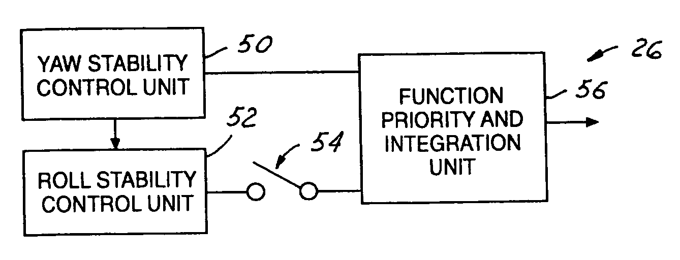
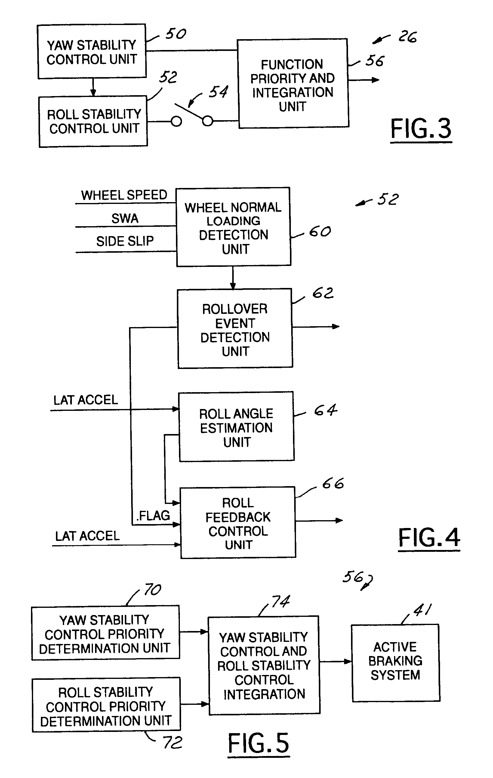
The present invention provides a way to add roll stability control to a vehicle's yaw stability control system. This can be done by either adding a separate function or integrating it with the yaw stability control strategy. The system uses sensors to measure various factors such as yaw rate, lateral acceleration, steering angle, and wheel speed to determine the appropriate control signals for yaw and roll stability. The integration unit then combines these signals to create a safety system control signal. The invention allows for improved stability and safety without requiring any changes to the standard yaw stability control system.

Problems solved by technology

Typically, the dynamic control systems do not address roll of the vehicle.
Although the vehicle attitude is well defined, direct measurement is usually impossible.
However, due to different control objectives for yaw stability and roll stability, the standard yaw stability control system will not directly or automatically improve vehicular roll stability.
Vehicle tests have shown that the standard yaw stability control system does not react properly to many on-road rollover events.
The roll stability control system, however, needs to make the vehicle under-steer more during the detected aggressive driving conditions that may contribute to vehicle roll instability.

Method used


Image

  • Enhanced system for yaw stability control system to include roll stability control function
  • Enhanced system for yaw stability control system to include roll stability control function
  • Enhanced system for yaw stability control system to include roll stability control function

Examples


Embodiment Construction

[0018]In the following figures, the same reference numerals will be used to identify the same components. The present invention is preferably used in conjunction with an existing yaw stability control system onto which the functionality of the roll stability control system is desired for a vehicle. Additionally, the present invention may also be used with a deployment device such as airbag. The present invention will be discussed below in terms of preferred embodiments relating to an automotive vehicle moving in a three-dimensional road terrain.

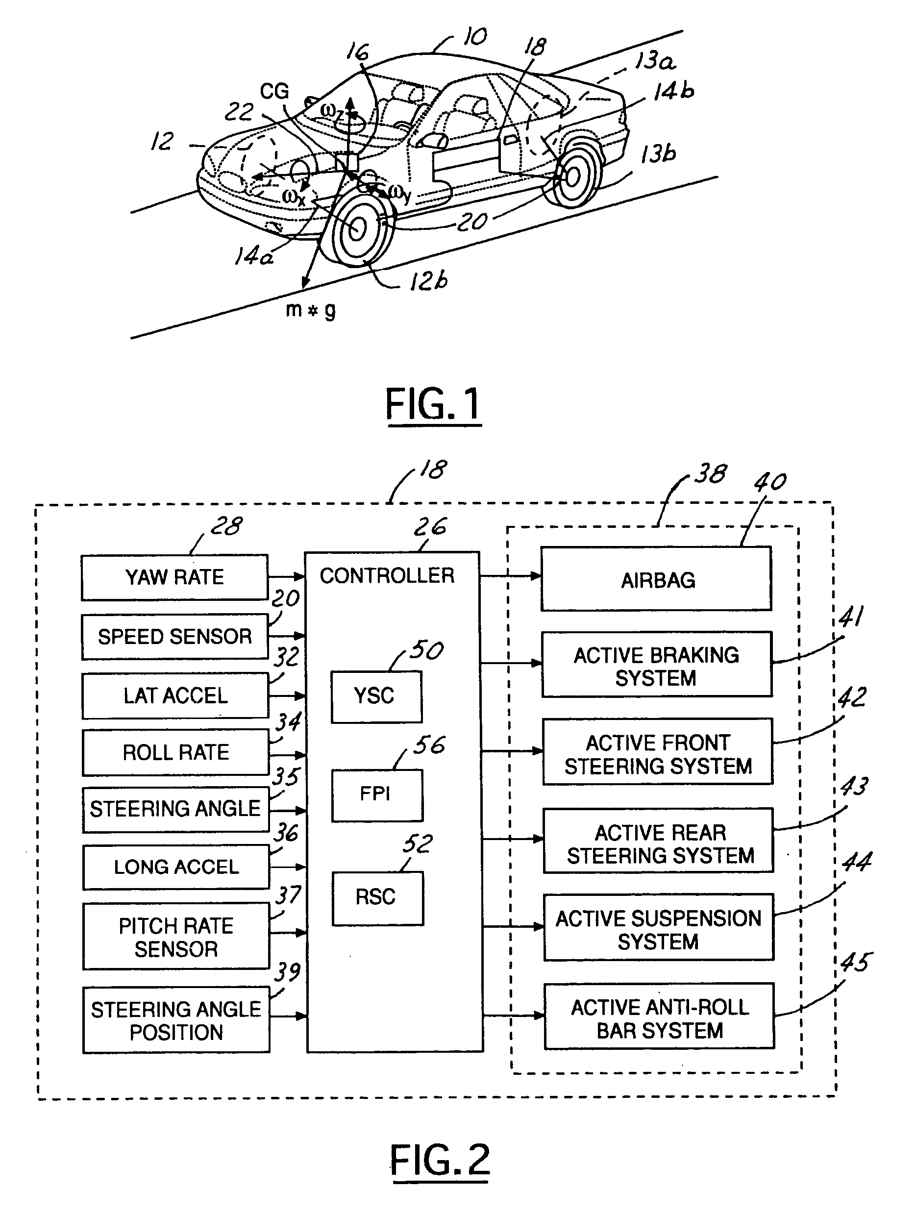
[0019]Referring to FIG. 1, an automotive vehicle 10 with a safety system of the present invention is illustrated with various forces and moments thereon. Vehicle 10 has front right and front left tires 12a and 12b, and rear right and left rear tires 13a and 13b, respectively. The vehicle 10 may also have a number of different types of front steering systems 14a and rear steering systems 14b, including having each of the front and rear wheels ...


PUM


Abstract

A yaw stability control system (18) is enhanced to include roll stability control function for an automotive vehicle and includes a plurality of sensors (28–39) sensing the dynamic conditions of the vehicle. The sensors may include a speed sensor (20), a lateral acceleration sensor (32), a yaw rate sensor (28) and a longitudinal acceleration sensor (36). The controller (26) is coupled to the speed sensor (20), the lateral acceleration sensor (32), the yaw rate sensor (28) and a longitudinal acceleration sensor (36). The controller (26) generates both a yaw stability feedback control signal and a roll stability feedback control signal. The priority of achieving yaw stability control or roll stability control is determined through priority determination logic. If a potential rollover event is detected, the roll stability control will take the priority. The controller for roll stability control function determines a roll angle of the vehicle from the lateral acceleration sensor signal and calculates the feedback control signal based on the roll angle.

Description

RELATED APPLICATIONS[0001]The present invention claims priority to provisional application No. 60 / 332,063 filed on Nov. 21, 2001, and is a continuation of non-provisional application Ser. No. 10 / 174,926 filed Jun. 19, 2002 now U.S. Pat. No. 6,654,674.TECHNICAL FIELD[0002]The present invention relates generally to a control apparatus for controlling a system of an automotive vehicle in response to sensed dynamic behavior, and more specifically, to a method and apparatus for controlling the yaw and roll motion of a vehicle.BACKGROUND[0003]Dynamic control systems for automotive vehicles have recently begun to be offered on various products. Dynamic control systems typically control the yaw of the vehicle by controlling the braking effort at the various wheels of the vehicle. Yaw control systems typically compare the desired direction of the vehicle based upon the steering wheel angle and the direction of travel. By regulating the amount of braking at each corner of the vehicle, the des...

Claims


Application Information

Patent Timeline
Patent Type & Authority Patents(United States)
IPC IPC(8): G06F7/00B60G17/0195B60T8/1755B60T8/24B62D6/04B62D7/15
CPCB60T8/1755B60T8/17554B60T8/243B60T8/246B62D6/04B62D7/159B60G17/0195B60G2800/925B60G2800/92B60G2800/962B60T2230/02B60T2230/03B60T2240/06B60T2260/022B60T2260/06B60G2400/0521B60G2400/0522B60G2400/0523B60G2400/104B60G2400/106B60G2400/204B60G2400/41B60G2800/016B60G2800/244B60G2800/246B60G2800/85B60G2800/91B60G2800/9122B60G2800/96
Inventor LU, JIANBOBROWN, TODD ALLENMEYERS, JOSEPH CARR
Owner FORD GLOBAL TECH LLC
Learn More