
Guard tour system incorporating a positioning system

a positioning system and monitor technology, applied in the field of guard tour monitor systems, can solve the problems of inability inconvenient use, and inability to allow guards to investigate with any flexibility, and achieve the effects of convenient system use, enhanced security features, and more flexibility in guard tours

Inactive Publication Date: 2006-04-11
TIMEKEEPING SYST
View PDF34 Cites 59 Cited by
  • Summary
  • Abstract
  • Description
  • Claims
  • Application Information

AI Technical Summary

Benefits of technology

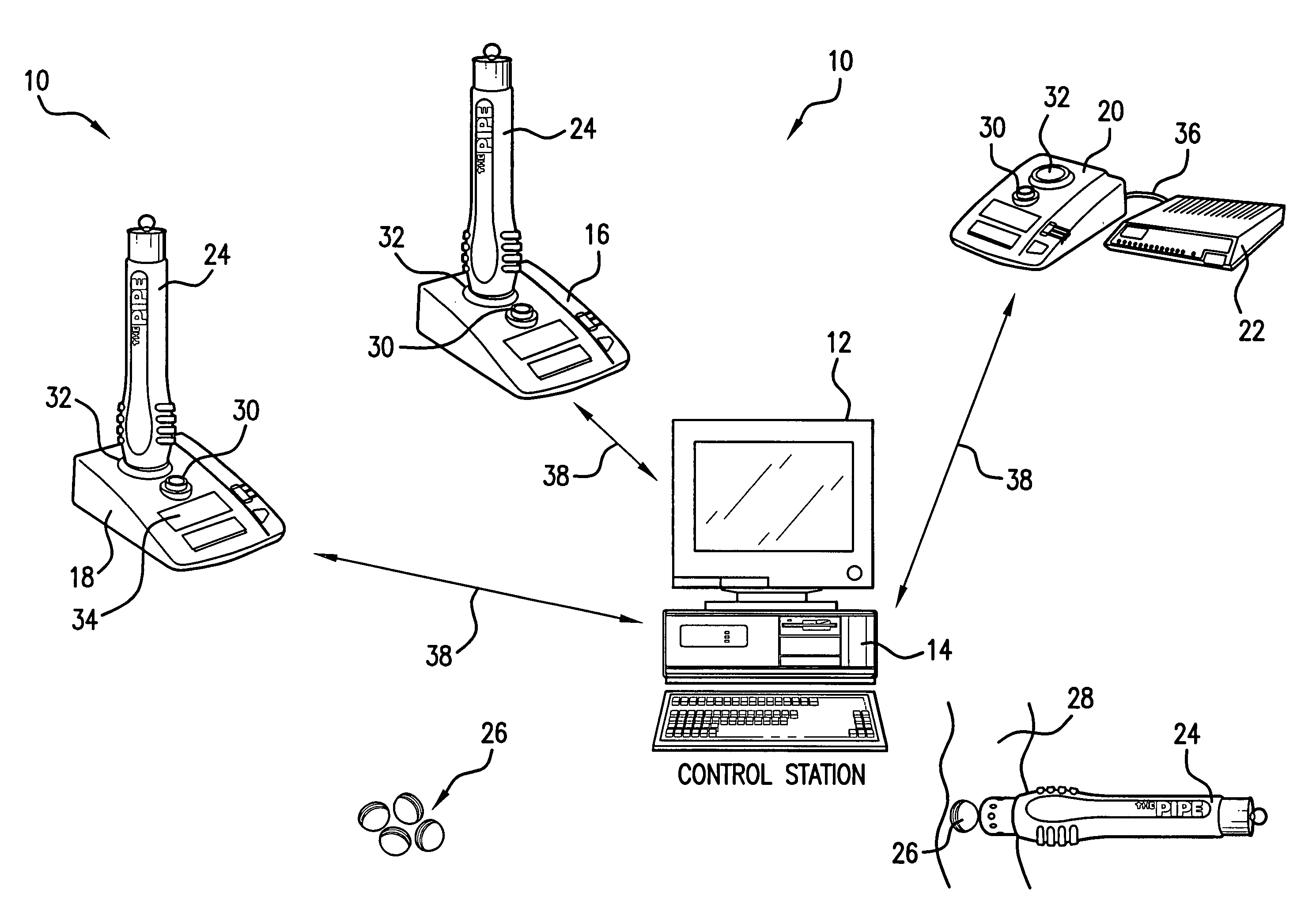
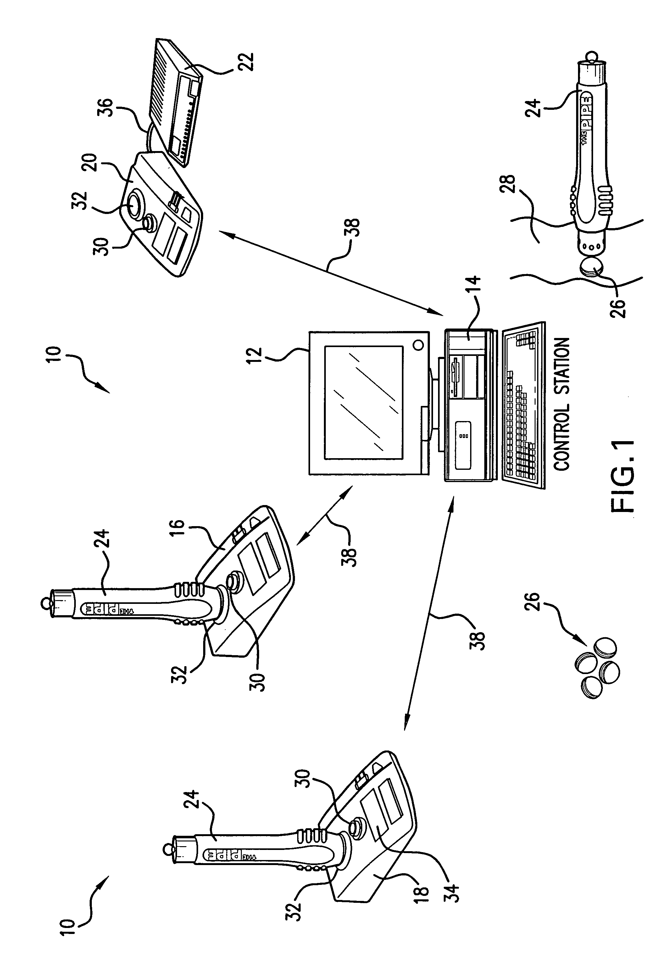
[0011]The software of the present invention automatically configures itself to be compatible with a variety of guard tour system hardware from other manufacturers. Therefore a company already using certain guard tour checkpoints and readers can easily use the system of the present invention.
[0013]The guard tour system of the present system may also include enhanced security features. Particularly, the present invention solves a deficiency of prior art systems that required a guard to visit each checkpoint in a predetermined sequence and in a prescribed amount of time. The present invention implements a method consisting of rules which allow more flexibility in guard tours.
[0015]Based on the foregoing, it is an object of the present invention to provide a guard tour system wherein guards can quickly and easily gather patrol information and transmit such information to a central location.

Problems solved by technology

However, this arrangement can be counterproductive.
This does not allow the guard any flexibility to investigate unusual occurrences he encounters during the tour, because he must proceed to the next checkpoint.
This is time consuming, and because it is done at the end of the tour, accuracy is sacrificed.
This is often a time consuming process, requiring some computer skills.

Method used


Image

  • Guard tour system incorporating a positioning system
  • Guard tour system incorporating a positioning system
  • Guard tour system incorporating a positioning system

Examples


Embodiment Construction

[0035]The present invention is fully described hereinafter with reference to the drawings, in which preferred embodiments of the invention are shown. The invention may also be embodied in many different forms and should not be construed as limited to only the disclosed embodiments. The provided embodiments are included so the disclosure will be thorough, complete and will fully convey the scope of the invention to persons of ordinary skill in the art.

[0036]A person of ordinary skill in the art would appreciate that the present invention may be embodied as a method, data processing system, or computer program product. As such, the present invention may take the form of an embodiment comprised entirely of hardware; an embodiment comprised entirely of software or an embodiment combining software and hardware aspects. In addition, the present invention may take the form of a computer program product on a computer-readable storage medium having computer-readable program code means embodi...


PUM


Abstract

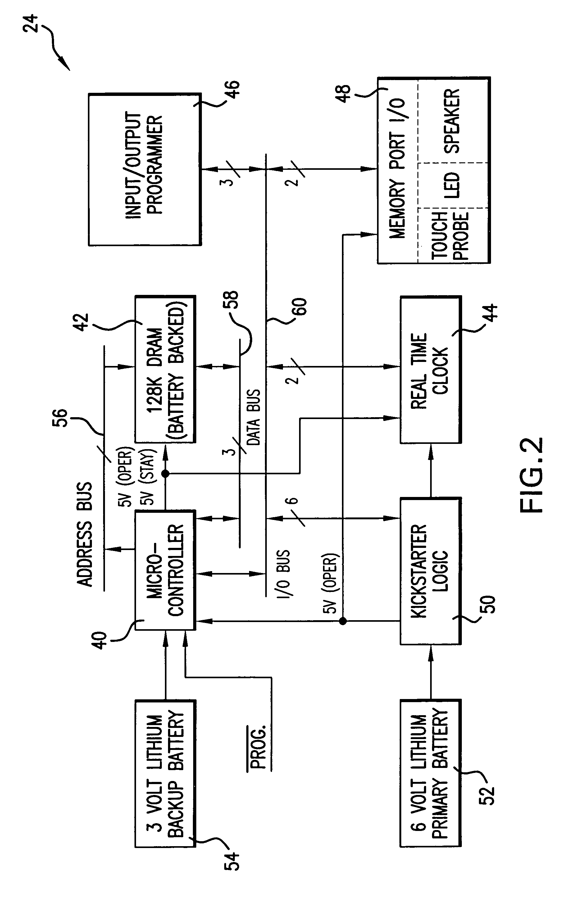
A guard tour system comprising a computer running a computer program that enables a variety of electronic hardware components to function as the guard tour system. It is contemplated that the computer program be multi-user and / or network compatible. The electronic hardware includes one or more touch button readers, or one or more positioning system receivers (such as a global or local positioning system receiver), or both; one or more downloaders for use with the touch button readers and global positioning system receivers; and optionally a plurality of touch memory buttons located along a guard tour. Each touch memory button includes preprogrammed information specific to its particular location. As a guard or night watchman progresses through the guard tour he or she either obtains a global positioning system location reading manually or automatically or reads the information stored within each touch memory button or both, using a hand-held, battery operated reader. The Global Positioning System allows for collection of various guard positioning information.

Description

[0001]This application is a Continuation-in-Part of Ser. No. 09 / 419,475 filed Oct. 15, 1999 now U.S. Pat. No. 6,834,259. Application Ser. No. 09 / 419,475 is hereby incorporated by reference herein.TECHNICAL FIELD[0002]The current invention relates to an improved guard tour monitor system. More specifically, the present invention relates to a system comprised of electronic hardware and software, that insures that patrol guards or officers monitor all desired areas of one or more buildings or property. In an embodiment, the system includes a positioning system which is used to acquire location and other information into the data acquired.BACKGROUND OF THE INVENTION[0003]At one time, guard tour systems consisted of mechanical clocks which used paper tape recording systems to time-stamp events of a tour. Another type of prior art guard tour system includes a bar code reader that is formed into a portable, hand-held device. Attached to each checkpoint are bar code labels. The guard or nig...

Claims


Application Information

Patent Timeline
IPC IPC(8): G06F15/00G07C1/20
CPCG07C1/20
Inventor MARKWITZ, BARRY J.CHRISS, DEAN
Owner TIMEKEEPING SYST
Learn More