
Method and system for solving finite element models using multi-phase physics

a multi-phase physics and finite element technology, applied in the direction of instruments, analogue processes for specific applications, electric/magnetic computing, etc., can solve the problems of less accurate, less accurate, and physical realistic results of finite difference techniques

Inactive Publication Date: 2006-04-11
LANDMARK GRAPHICS CORP
View PDF45 Cites 40 Cited by
  • Summary
  • Abstract
  • Description
  • Claims
  • Application Information

AI Technical Summary

Benefits of technology

[0007]One or more of the problems outlined above may be solved by the various embodiments of the invention. Broadly speaking, the invention comprises systems and methods for solving finite element models, wherein the matrix that governs the solution is modified so that it satisfies the properties of monotonicity and preservation of linearity. This is accomplished by adjusting the weighting coefficients of the matrix so that the elements which lie on the diagonal of the matrix are non-negative and the elements which are off the diagonal are non-positive. This causes the solution to be both more accurate than traditional finite difference techniques and more realistic than traditional finite element techniques.

Problems solved by technology

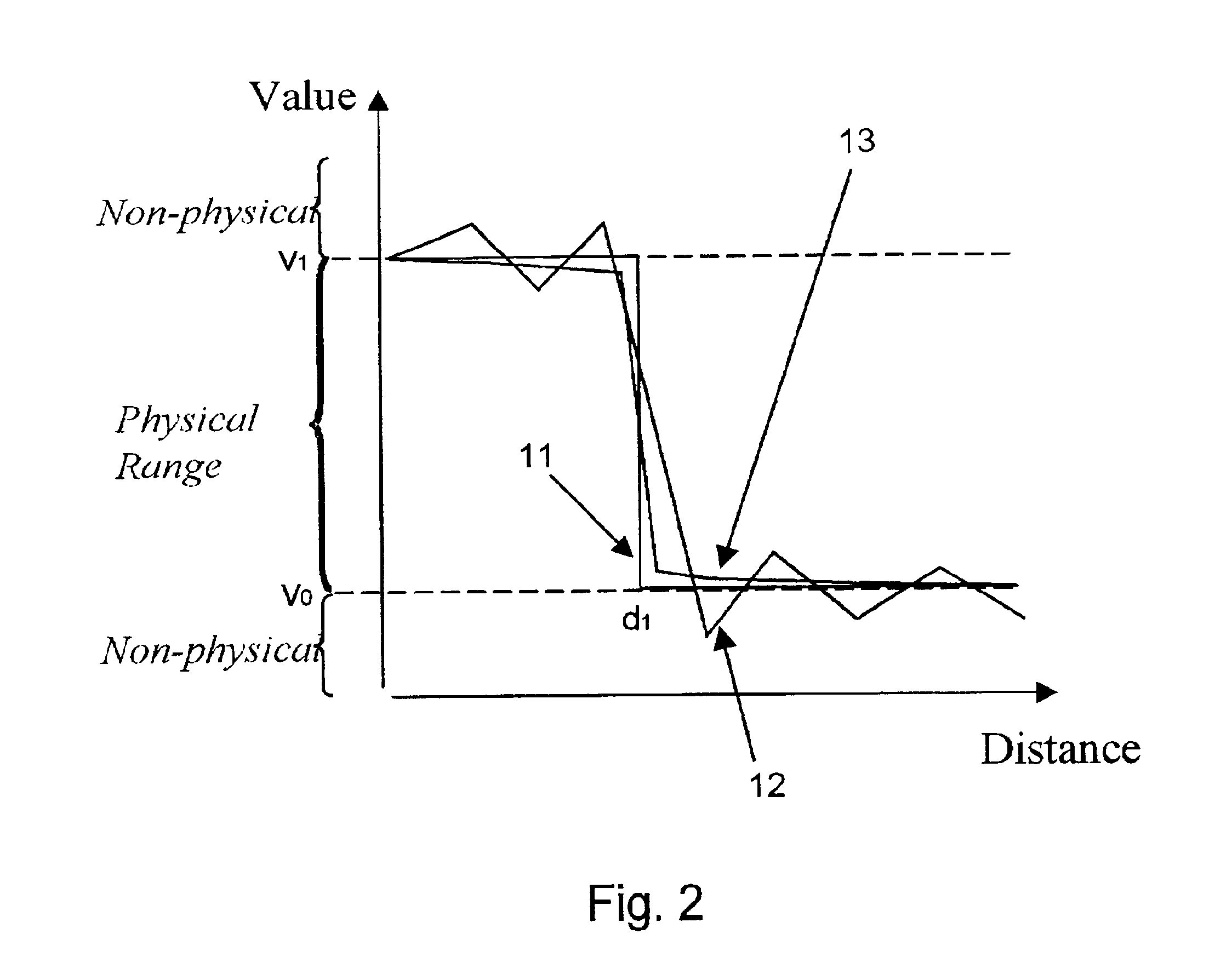
Generally speaking, the finite difference techniques produce physically realistic results, but they are not very accurate.
The finite element techniques, on the other hand, are more accurate, but they produce results which are not physically realistic.
As a result of their respective disadvantages, both the finite difference techniques and finite element techniques which are conventionally used normally require a great deal of computer resources.
This increases the amount of memory and CPU time which are needed to compute an accurate solution.
In the case of finite element techniques, comparable accuracy can be achieved with fewer nodes, but the solutions may not be realistic.
Consequently, there may be problems for which the solution does not converge, or for which the solution may converge very slowly.
These techniques are therefore less reliable and may require a large number of iterations before acceptable accuracy is achieved.

Method used


Image

  • Method and system for solving finite element models using multi-phase physics
  • Method and system for solving finite element models using multi-phase physics
  • Method and system for solving finite element models using multi-phase physics

Examples


Embodiment Construction

[0023]A preferred embodiment of the invention is described below. It should be noted that this and any other embodiments described below are exemplary and are intended to be illustrative of the invention rather than limiting.

[0024]Broadly speaking, the invention comprises methods for solving finite element models, wherein the solution is guaranteed both to be monotonic and to satisfy linearity preservation. This ensures that the solution will be both accurate and realistic. The monotonicity and the linearity of the solution are ensured by generating a matrix for the solution of the finite element model such that the elements of the matrix which are on the diagonal are non-negative, and the elements which are off-diagonal are non-positive. This matrix can then be solved using conventional finite element techniques to generate the desired accurate, realistic solution.

[0025]The present methods provide a number of advantages over traditional finite element and finite difference techniqu...


PUM


Abstract

Systems and methods for solving finite element models, wherein the matrix that governs the solution is modified by adjusting the weighting coefficients of the matrix so that the elements which lie on the diagonal of the matrix are non-negative and the elements which are off the diagonal are non-positive. In one embodiment, a system is discretized on a finite element mesh with the contribution of each node to the discretization being weighted based upon the direction of fluid flow across each element. The nodes which are upstream from the other nodes of the respective elements are weighted more heavily to cause the resulting matrix to be substantially diagonal. This matrix is solved using traditional techniques.

Description

RELATED APPLICATIONS[0001]This application claims priority under 35 U.S.C. § 119(e) to U.S. Patent Application No. 60 / 215,697 entitled “Method and System for Oil Reservoir Simulation and Modeling” by Stephen R. Kennon, Kok Thye Lim, Scott A. Canaan, Steven B. Ward, Stuart W. Pond, Jr. and Edward J. Barragy, filed Jun. 29, 2000, which is incorporated by reference as if set forth in its entirety herein.FIELD OF THE INVENTION[0002]The invention relates generally to methods for modeling physical systems using finite element analysis and, more specifically, to methods for solving finite element models wherein the matrix that controls the solution for the model is configured to maintain the properties of monotonicity and linearity preservation.BACKGROUND OF THE INVENTION[0003]Physical systems can be modeled mathematically to simulate their behavior under certain conditions. There are a wide variety of means to model these systems, ranging from the very simplistic to the extremely complica...

Claims


Application Information

Patent Timeline
Patent Type & Authority Patents(United States)
IPC IPC(8): G06F7/60E21B44/00G01V11/00G06F17/13G06F17/16G06F17/50G06F19/00G06T17/05G06T17/20
CPCG01V11/00G06F17/5004G06T17/20G06T17/05G06F17/5018G06F30/13G06F30/23
Inventor KENNON, STEPHEN R.
Owner LANDMARK GRAPHICS CORP
Learn More