
Wrist driving mechanism for robot

a technology of driving mechanism and wrist, which is applied in the direction of joints, load-engaging elements, thin material handling, etc., can solve the problems of reducing the controllability of the robot and increasing the weight of the robot arm, and achieves the effect of improving the wrist driving mechanism of the robot and ensuring the placement of cables and/or wrists

Active Publication Date: 2006-04-18
FANUC LTD
View PDF17 Cites 14 Cited by
  • Summary
  • Abstract
  • Description
  • Claims
  • Application Information

AI Technical Summary

Benefits of technology

[0006]An object of the present invention is to improve the wrist driving mechanism for the robot such that a sufficient space for arranging cables and / or wrist is provided in the robot arm.
[0007]Another object of the present invention is to improve the wrist driving mechanism such that driving sources for the three axes of the wrist driving mechanism are enabled to be mounted on a wrist mounting base to avoid complication of the wrist driving mechanism.

Problems solved by technology

However, if the diameters of the drive shafts are made larger, a diameter of the robot arm is made greater to increase a possibility of causing an interference between the robot arm and a peripheral device in an operation of the robot.
Further, weight of the robot arm increases to lower controllability of the robot.

Method used


Image

  • Wrist driving mechanism for robot
  • Wrist driving mechanism for robot
  • Wrist driving mechanism for robot

Examples


Embodiment Construction

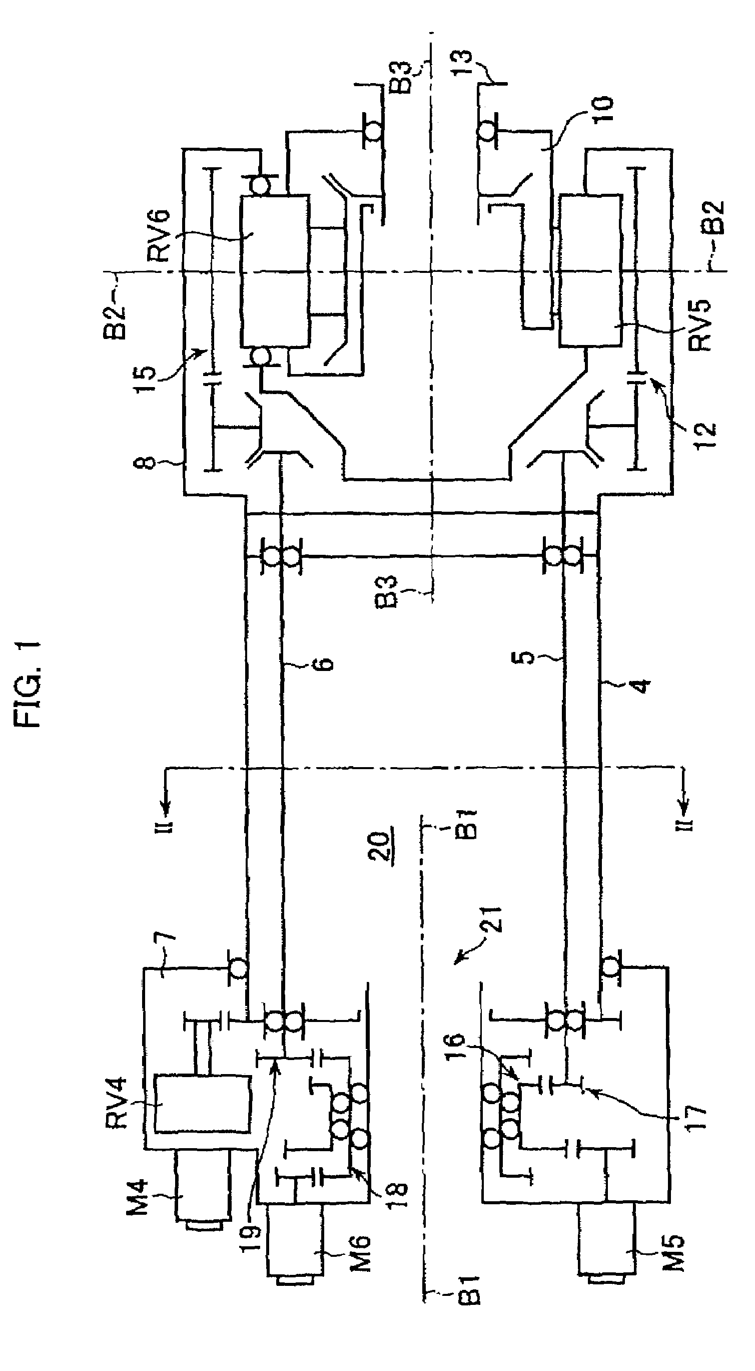
[0016]FIG. 1 schematically shows a robot wrist driving mechanism for driving a wrist mechanism provided at a distal end of a robot arm according to an embodiment of the present invention.

[0017]The robot wrist mechanism has three degrees of freedom around three different wrist axes of a first axis B1, a second axis B2 and a third axis B3, and a first motor M4, a second motor M5 and a third motor M6 are provided at a proximal portion of a robot arm as driving sources of the three wrist axes B1, B2 and B3, respectively.

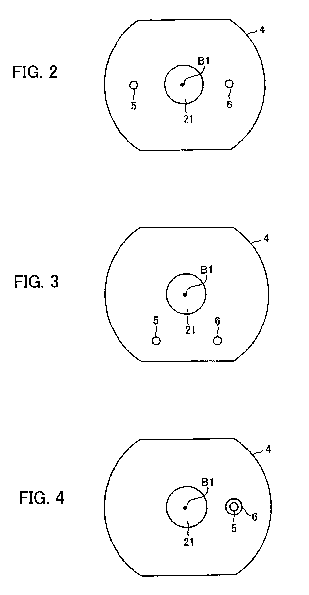
[0018]Three drive shafts of a first drive shaft 4, a second drive shaft 5 and a third drive shaft 6 are used for transmitting driving power of the first, second and third motors M4, M5 and M6 to first, second and third wrist elements 8, 10 and 13, respectively. The first drive shaft 4 is an elongated hollow shaft having a diameter larger than those of the second and third drive shafts 5 and 6. The second drive shaft 5 and the third drive shaft 6 are arranged in an inner ...


PUM


Abstract

A wrist driving mechanism capable of arranging a large amount of cables and pipes in a robot arm. A robot wrist mechanism having three degrees of freedom is driven by first, second and third drive shafts for transmitting driving forces of first, second and third motors M4, M5 and M6, respectively. The first drive shaft is a hollow shaft for transmitting a rotational driving force from the motor M4 to a first wrist element supported rotatably around the first axis B1. The second and third drive shafts are arranged eccentrically with the first axis B1 in an inner space of the first drive shaft. The second drive shaft transmits a rotational driving force from the motor M5 to a second wrist element supported rotatably around the second axis B2, and the third drive shaft transmits a rotational force from the motor M6 to a third wrist element supported rotatably around the third axis B3. A first gear and a third gear as planet gears and a second gear and a fourth gear as sun gears are provided for avoiding complication of structure due to the eccentric arrangement of the second and third drive shafts.

Description

BACKGROUND OF THE INVENTION[0001]1. Field of the Invention[0002]The present invention relates to a driving mechanism of a wrist of a robot, and in particular to a technique for securing a sufficient space for arranging cables / pipes for supplying energy and / or fluid to a tool to be attached to an end of the wrist without complication of structure of the driving mechanism.[0003]2. Description of Related Art[0004]There is known a wrist driving mechanism having three degrees of freedom around three axes and a space for arranging cables / popes in a robot arm, as disclosed in JP 2000-334689A and EP 0873826B1. In the prior art, hollow drive shafts having different diameters for the three axes are concentrically arranged along an axis of rotation of the robot arm for providing the space for arranging the cables / pipes in the inner hollow shaft.[0005]In the above structure, in order to arranging a large number of cables / pipes in the space in the inner hollow drive shaft, it is necessary to des...

Claims


Application Information

Patent Timeline
IPC IPC(8): B25J17/00B25J17/02B25J18/00
CPCB25J17/0283Y10T74/20329Y10T74/20335Y10S414/131
Inventor UEMATSU, MASAAKIMATSUMOTO, KUNIYASUNAKAGAWA, HIROSHIMORIOKA, MASAHIRO
Owner FANUC LTD
Learn More