Gas decompression device for fuel cell system

a fuel cell and gas decompression technology, which is applied in the direction of fluid pressure control, process and machine control, instruments, etc., can solve the problems that the air pressure needed for the conventional regulator cannot be supplied to the conventional regulator separately, the outlet pressure declines, and the conventional regulator cannot evade the influence of a spring, so as to achieve constant gas pressure supplied to the fuel cell

Inactive Publication Date: 2006-04-18
AISAN IND CO LTD
View PDF10 Cites 6 Cited by
  • Summary
  • Abstract
  • Description
  • Claims
  • Application Information

AI Technical Summary

Benefits of technology

[0008]Accordingly, the present invention has been made to resolve problems described in the above. It is a primary object of the present invention to provide a decompression device for fuel cell system capable of making gas pressure supplied to a fuel cell constant. In addition to the primary object, a secondary object of the present invention is to provide a decompression device for fuel cell system capable of declining gas pressure acting on a fuel cell when fuel cell system is stopped.

Problems solved by technology

However, the conventional regulator cannot evade influence of a spring constant, and its outlet pressure declines in case large amount of hydrogen gas flows into the regulator.
Therefore, air pressure needed for the regulator cannot be supplied to the regulator separately.
As a result, it is difficult to adjust outlet pressure of hydrogen gas in the regulator as desired.
Such pressure proof design makes the entirety of a device grow in size and period of endurance tends to be shortened.

Method used


Image

  • Gas decompression device for fuel cell system
  • Gas decompression device for fuel cell system
  • Gas decompression device for fuel cell system

Examples


Embodiment Construction

[0022]There will be described an embodiment of the inventive gas decompression device for fuel cell system by referring to drawings.

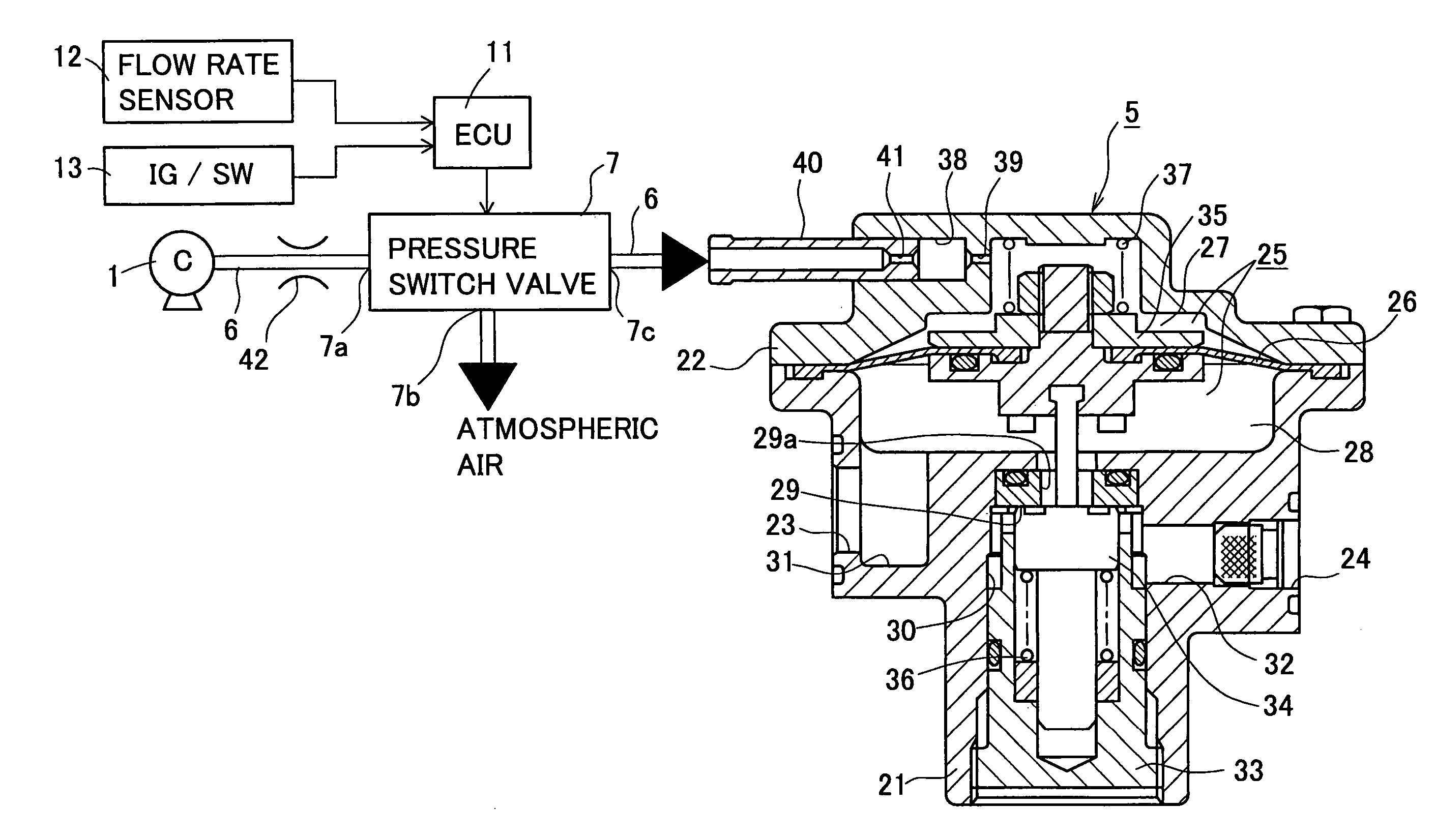
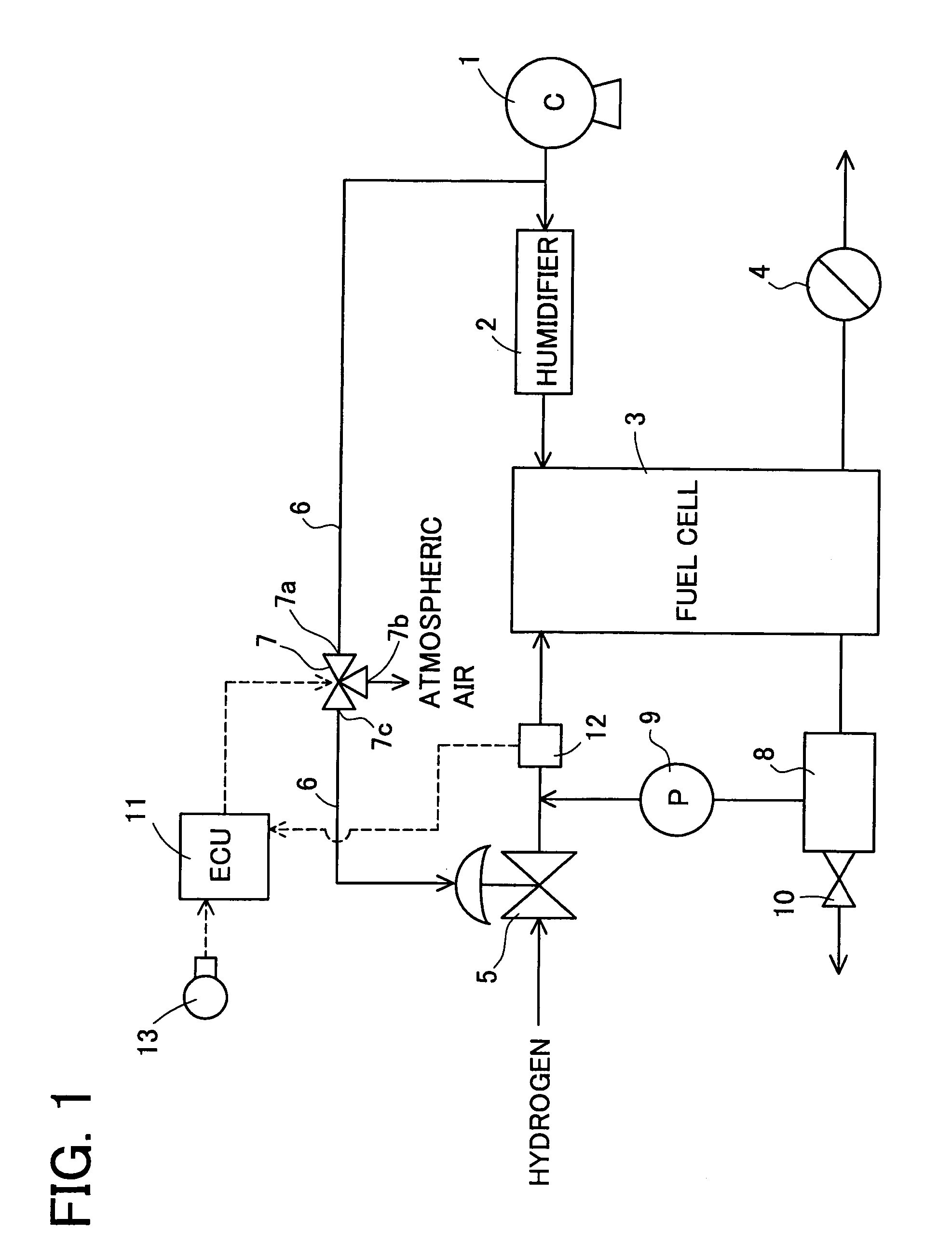
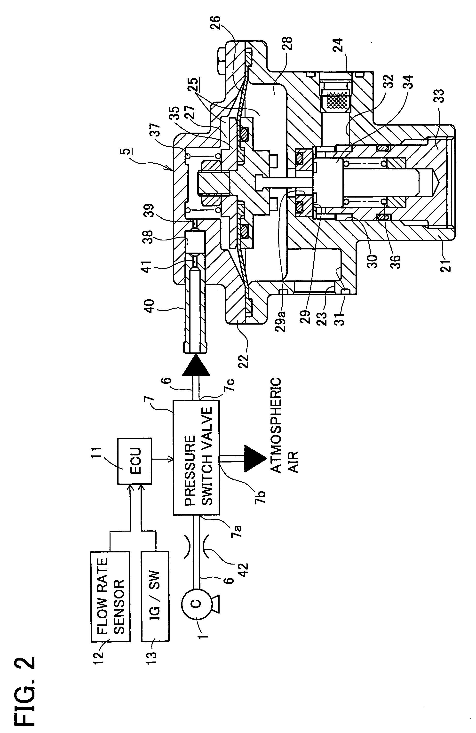
[0023]FIG. 1 shows a schematic structure diagram of fuel cell system including a gas decompression device directed to the embodiment. In the fuel cell system, air as oxidizing gas is recompressed to reach predetermined pressure level by a compressor 1. Recompressed air is humidified by a humidifier 2 and supplied to a fuel cell 3. Air supplied and used for generating electricity at the fuel cell 3 is exhausted as air-OFF gas from there and exhausted outside through a pressure control valve 4. The pressure control valve 4 controls air supply pressure at the fuel cell 3. In this fuel cell system, hydrogen gas as fuel gas is decompressed by a decompression valve 5 and supplied to the fuel cell 3. Flow rate of hydrogen gas (gas flow rate) supplied to the fuel cell 3 is detected by a flow rate sensor 12. The decompression valve 5 comprises a pneumatic propor...


PUM

PropertyMeasurementUnit
pressureaaaaaaaaaa
gas flow rateaaaaaaaaaa
flow rateaaaaaaaaaa

Abstract

A decompression valve incorporated in a gas decompression device valve of fuel cell system is divided into a measuring room and a back pressure room by a diaphragm. A valve seat and a valve body adjoining to the measuring room are arranged on the decompression valve. When gas pressure works on the diaphragm, the diaphragm is displaced to move in a direction for making the valve body closer to the valve seat. Pressure control springs arranged on the decompression valve urge the diaphragm in a direction to make the valve body separate from the valve seat. The diaphragm, pressure control springs and the like allow hydrogen gas to pass the valve seat, whereby hydrogen gas from an outlet is decompressed. The gas decompression further comprises a pressure switch valve which adjusts urging force of the pressure control spring by back pressure, a flow rate sensor which detects gas flow rate at the outlet, and an electronic control unit which controls the pressure switch valve so as to adjust back pressure depending on gas flow rate.

Description

BACKGROUND OF THE INVENTION[0001]1. Field of the Invention[0002]The present invention relates to a gas decompression device for fuel cell system which is used for decompressing fuel gas or oxidizing gas supplied to a fuel cell in fuel cell system.[0003]2. Description of Related Art[0004]JP Laid-open Patent Publication No. 2002-373682 (pp. 3–6, FIG. 1 and FIG. 2) discloses a conventional gas decompression device. Fuel cell system disclosed in No. 2002-373682 employs a regulator for reducing pressure of fuel gas (hydrogen gas) supplied to a fuel cell depending on pressure of air supplied to the fuel cell. The regulator comprises a pneumatic proportional pressure control valve wherein air supplied from an air compressor to a fuel cell is used, and a pressure signal of the supplied air is inputted so that pressure of hydrogen gas at an outlet (outlet pressure) should be reduced to a predetermined range of pressure depending on the pressure signal. Generally, this type of regulator has a...

Claims


Application Information

Patent Timeline
Patent Type & Authority Patents(United States)
IPC IPC(8): G05D7/06G05D16/20H01M8/04G05D16/06
CPCG05D16/0663Y10T137/7761Y10T137/7836Y10T137/7782
Inventor ANDO, AKIRA
Owner AISAN IND CO LTD
Why Eureka
Try Eureka