Water stop for a loop installation in a pre-insulated pipeline

a loop installation and pre-insulated technology, applied in the direction of pipe elements, pipe connection arrangements, mechanical equipment, etc., can solve the problems of deterioration of foam, inadvertent puncture of protective jackets of insulated pipelines, and the enemy of foamed systems

Active Publication Date: 2006-04-18
THERMACOR PROCESS
View PDF13 Cites 17 Cited by
  • Summary
  • Abstract
  • Description
  • Claims
  • Application Information

AI Technical Summary

Benefits of technology

[0011]The present invention has as its general purpose to provide a system for effectively isolating a section of pre-insulated piping in the case o

Problems solved by technology

Ground water is the enemy of foamed systems.
The protective jacket of the insulated pipeline may also be punctured inadvertently by maintenance or construction op

Method used


Image

  • Water stop for a loop installation in a pre-insulated pipeline
  • Water stop for a loop installation in a pre-insulated pipeline
  • Water stop for a loop installation in a pre-insulated pipeline

Examples


Embodiment Construction

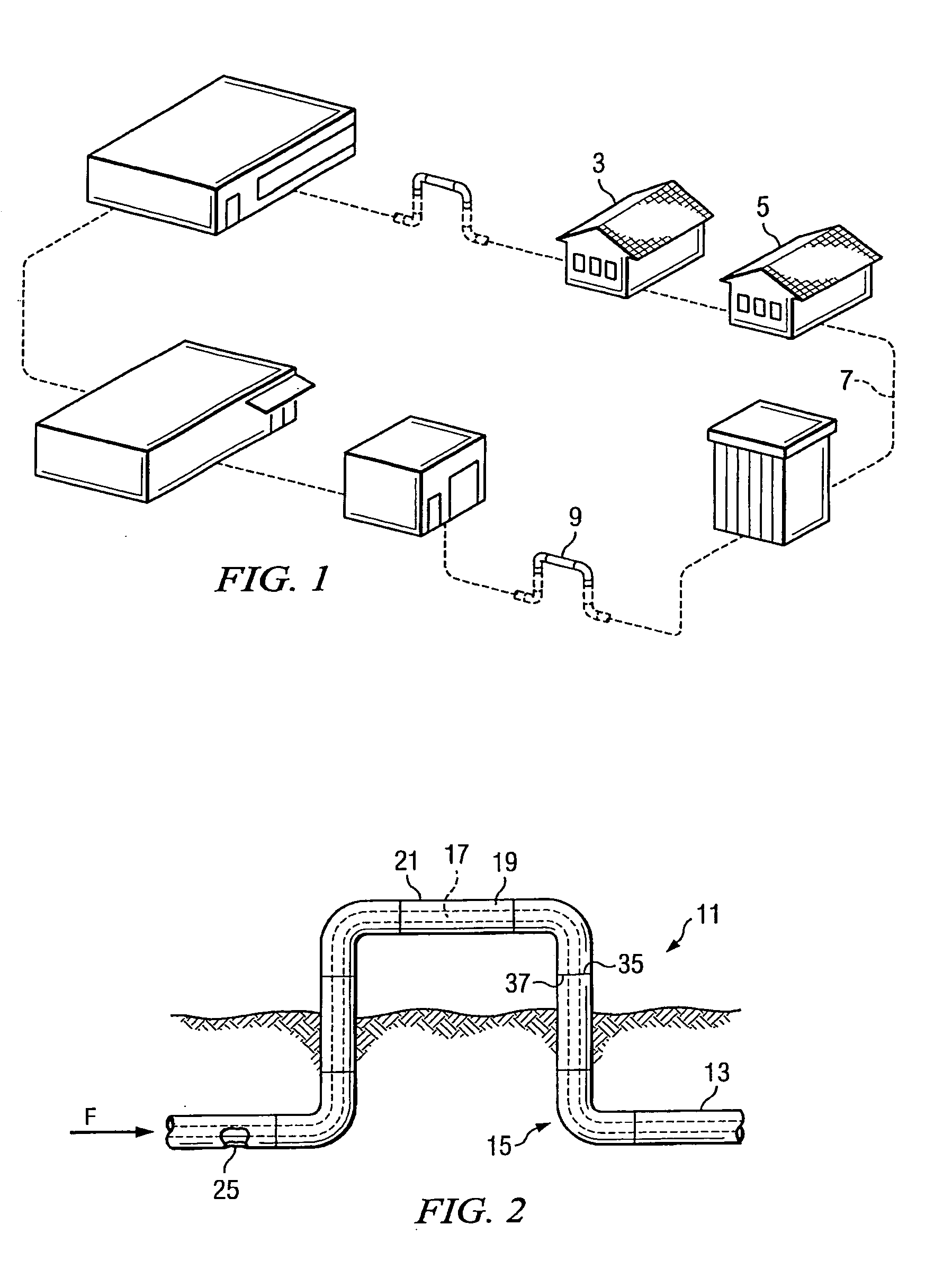
[0020]Turning first to FIGS. 1–2, there is illustrated a typical environment in which the pre-insulated piping systems of the invention might be employed. FIG. 1 shows a school campus having a number of isolated buildings 3, 5 connected by an underground insulated pipeline carrying steam which at points includes right angle loops or elbows 9.

[0021]FIG. 2 is a schematic view of the standard piping installation of the type under consideration designated generally as 11. The installation 11 includes a number of coaxially oriented lengths of pipe, such as length 13 (shown broken away in FIG. 2). The installation may also include a number of angled fittings such as the right angle elbows (generally shown as 15) in FIG. 2. Each length of pipe includes an inner pipe 17, typically formed of steel, an envelope of foamed insulation 19 surrounding the inner pipe and outer protective jacket 21 surrounding the envelope of insulation. The joining ends (shown generally as 35, 37 in FIG. 2) of adja...


PUM

PropertyMeasurementUnit
Temperatureaaaaaaaaaa
Fractionaaaaaaaaaa

Abstract

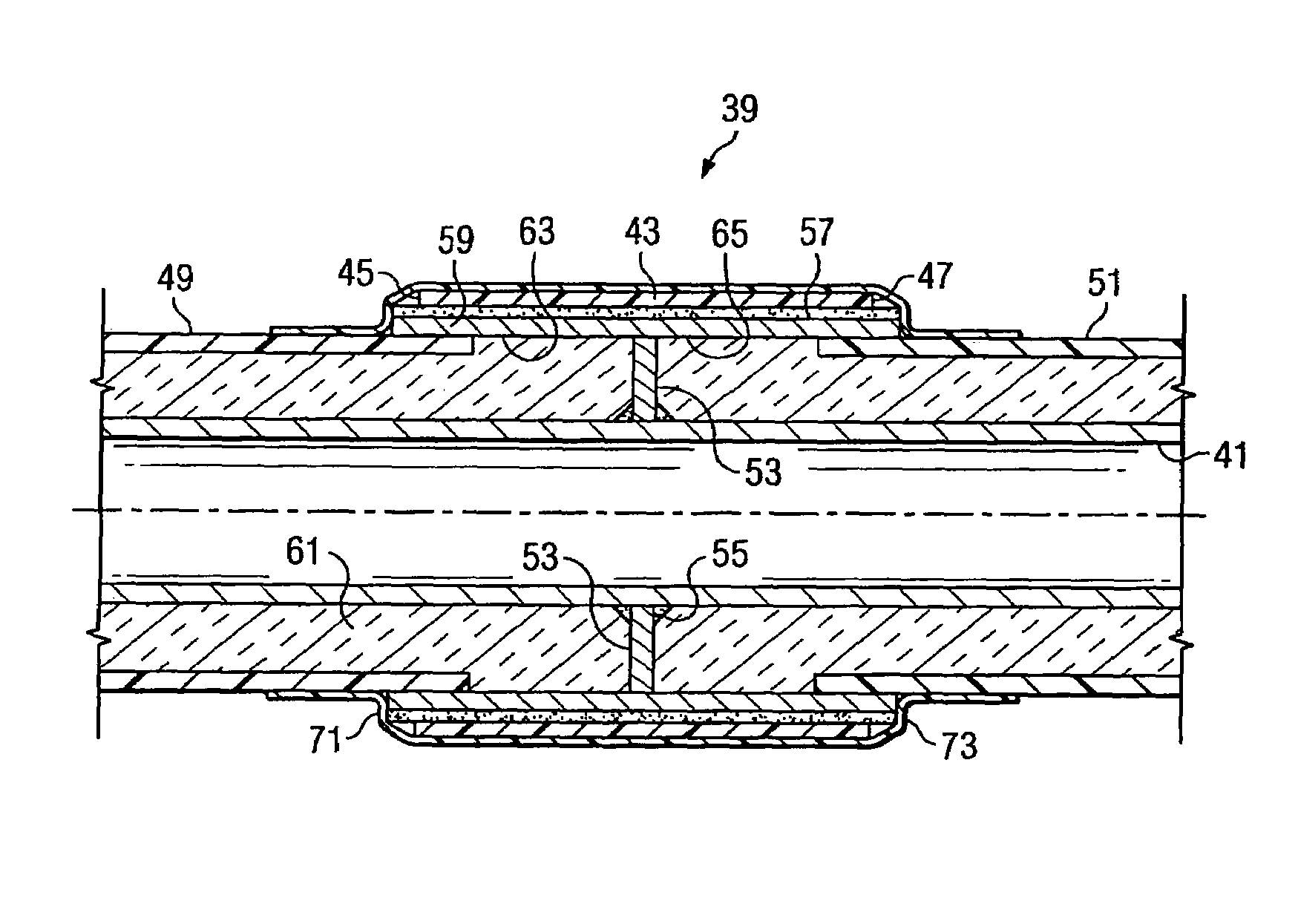
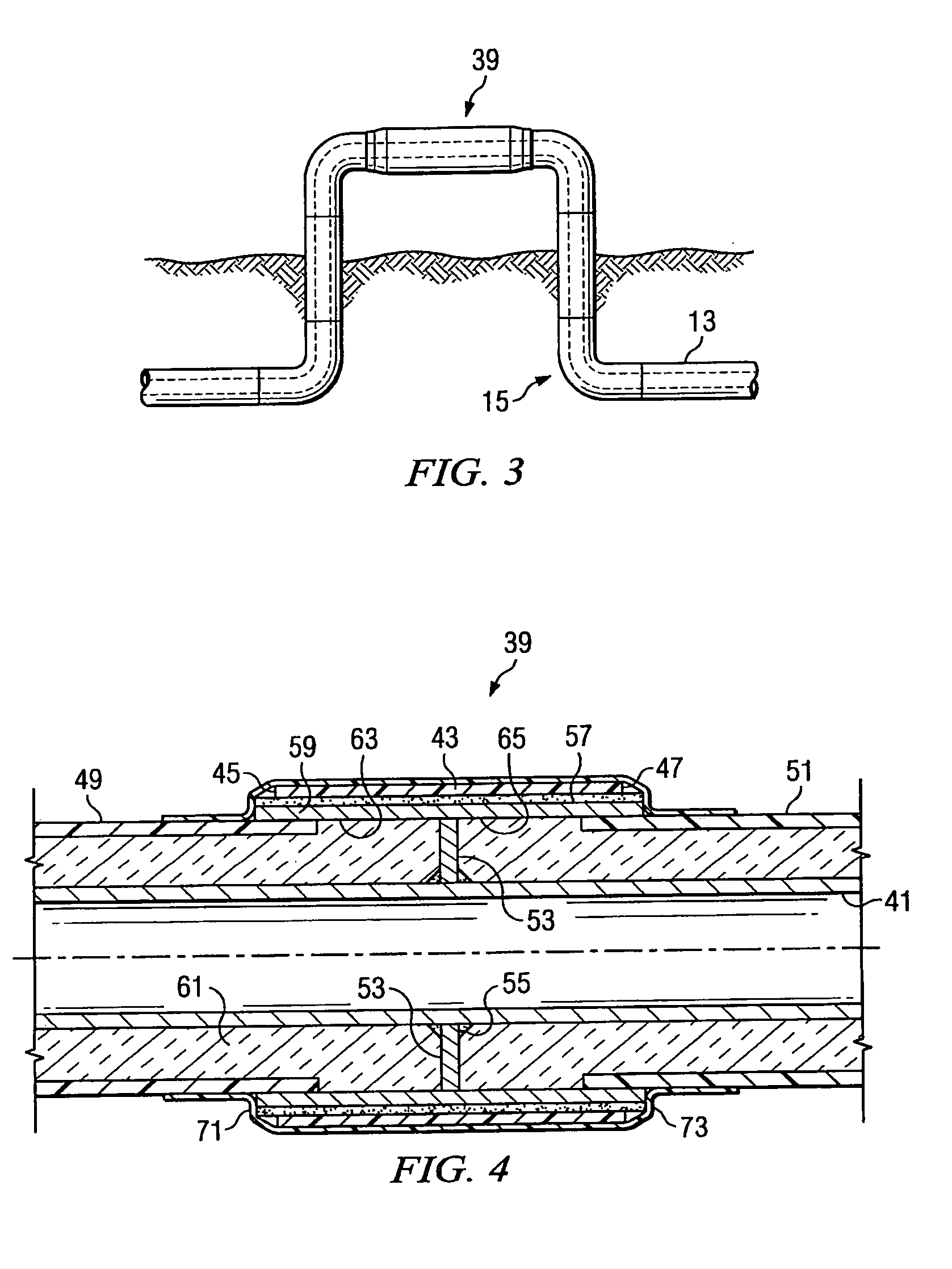
A high temperature pre-insulated piping system is shown which has a special water stop located along the length of the piping. The water stop has an internal disk which forms a pair of isolated chambers within the water stop. The internal disk is formed of a material which is impervious to the flow of water. As a result, the two internal chambers are isolated from one another and act as isolating elements to contain any breach in the exterior of the piping system to a specific location in the length of the pipe string.

Description

BACKGROUND OF THE INVENTION[0001]1. Field of the Invention[0002]The present invention relates to pre-insulated piping systems, and more specifically to a method for isolating a section of piping in the case of a breakdown of the insulation in the presence of water or other contaminants or under thermal movement stresses.[0003]2. Description of the Prior Art[0004]There are many instances in which insulated pipelines are needed. For example, distributed HVAC (heating, ventilation and air conditioning) applications utilize chilled water for cooling and steam for heating. The chiller and boiler are typically contained in a central location and the chilled water and steam are distributed to other locations. For example, on a school campus, the chiller and boiler may be located in a power plant building. The chilled water and steam are distributed to classrooms in separate buildings.[0005]A set of insulated pipelines is used to convey the chilled water from the chiller to other locations ...

Claims


Application Information

Patent Timeline
IPC IPC(8): F16L59/14
CPCF16L59/15F16L59/166F16L47/22
Inventor KEYES, THOMAS JOSEPH
Owner THERMACOR PROCESS
Why Eureka
Try Eureka