Vehicle lifting platform

Inactive Publication Date: 2006-04-18
MASCHENBAU HALDENWANG
View PDF31 Cites 6 Cited by
  • Summary
  • Abstract
  • Description
  • Claims
  • Application Information

AI Technical Summary

Benefits of technology

[0007]It is a primary purpose of the invention to provide a technically simple lifting platform for vehicles which requires little space, can be produced at low cost, can be operated with little maintenance, and at the same time fully satisfies the prevailing safety requirements.

Problems solved by technology

Even though such lifting platforms fully satisfy the operational and safety technical requirements, the manufacturing costs are substantial, which are caused by the technically complex lifting systems.

Method used


Image

  • Vehicle lifting platform
  • Vehicle lifting platform
  • Vehicle lifting platform

Examples


Embodiment Construction

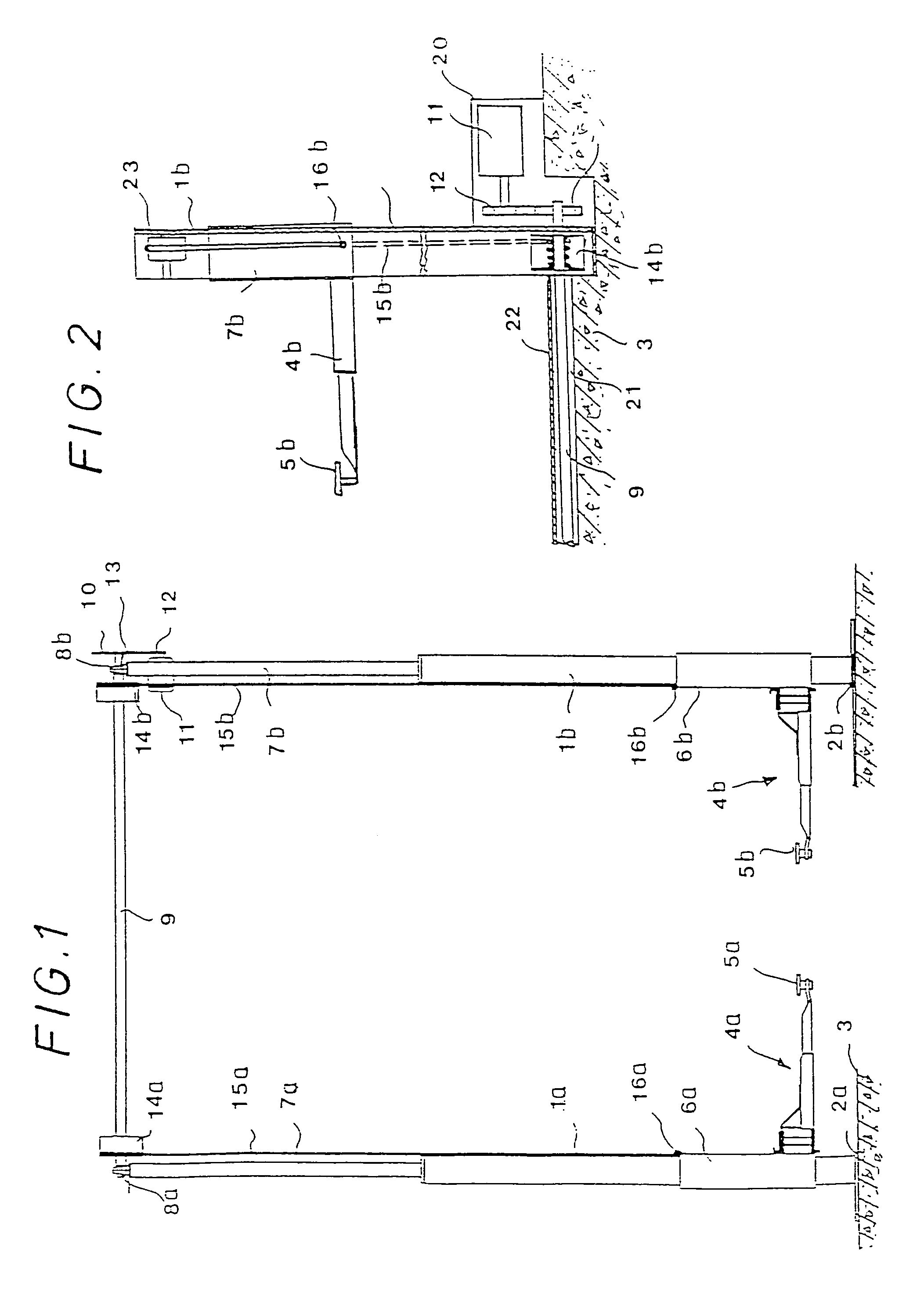
[0020]The two-column lifting platform according to FIG. 1 is designed for two-track vehicles, particularly passenger cars, and comprises two columns, 1a and 1b, which are fixedly anchored in floor foundation 3 with associated bases 2a and 2b. On each of columns 1a and 1b is a horizontal support arm, 4a and 4b, respectively, arranged so as to be vertically shiftable. Each of support arms 4a and 4b is extensible in a telescope-like manner and each is provided with a support 5a and 5b respectively, at its end. Each of the support arms is attached to a vertical guide, 6a and 6b, respectively, at its end which at least partly encloses the respective columns 1a and 1b in the illustrated embodiment. The length of guides 6a and 6b ensures a tilt-free support of the support arms even with a vehicle driven on, as well as ensuring their free movement.

[0021]On each of columns 1a and 1b, a stable elongation beam 7a and 7b, respectively, is provided comprising upper bearing 8a and 8b, respectivel...


PUM


Abstract

A lifting platform for vehicles having at least one column, at least one support arm shiftable on the column by vertical guides and having supports. The lifting platform also includes a prime mover having switching and control elements and a transmission disposed between the prime mover and the associated support arm, the transmission having at least one flexible traction cable coupled to a rotating member positioned at the upper end of the respective column and to the associated support arm.

Description

CROSS-REFERENCE TO RELATED APPLICATION[0001]This application is a divisional of U.S. patent application Ser. No. 09 / 942,400 filed 29 Aug. 2001 now U.S. Pat. No. 6,863,159.BACKGROUND[0002]1. Field of the Invention[0003]The invention relates to a lifting platform and more particularly to a vehicle lifting platform having a flexible traction cable coupling an electric motor to support arms.[0004]2. Background Discussion[0005]Conventional lifting platforms for motor vehicles generally function according to the lifting strut principle, the lifting shear principle or the toothed rack or jack screw principle. Even though such lifting platforms fully satisfy the operational and safety technical requirements, the manufacturing costs are substantial, which are caused by the technically complex lifting systems.[0006]Accordingly, there is a need for a vehicle lifting platform with reduced complexity and manufacturing costs. The present invention satisfies these needs and provides related advant...

Claims


Application Information

Patent Timeline
IPC IPC(8): B66F7/02
CPCB66F7/02
Inventor RAUCH, WINFRIED
Owner MASCHENBAU HALDENWANG
Why Eureka
Try Eureka