Metal wood club with improved hitting face

a golf club and metal wood technology, applied in the field of improved golf club head, can solve the problems of high dependence on the accuracy of conventional clubs, no teaching alignment, and inability to adjust, and achieve the effects of high flexural stiffness, high resilience, and high coefficient of restitution

Inactive Publication Date: 2006-04-18
ACUSHNET CO
View PDF246 Cites 266 Cited by
  • Summary
  • Abstract
  • Description
  • Claims
  • Application Information

AI Technical Summary

Benefits of technology

[0013]This arrangement of inner and intermediate zones forms an area of relatively high flexural stiffness in the direction of high heel to low toe, thereby creating high resilience in the direction of high toe to low heel. In other words, this arrangement creates a gradient of flexural stiffness in the direction of high toe to low heel, and produces a desirable effect of manipulating resilience or higher coefficient of restitution (COR) in that direction. This area of improved coefficient of restitution advantageously coincides with the ball impact pattern that golfers typically make on the hitting face.

Problems solved by technology

However, these environmental effects are beyond the control of the golf equipment manufacturer.
Furthermore, the accuracy of conventional clubs is highly dependent on impact location.
However, there is no teaching to align the coefficient of restitution of the golf club head to the ball impact pattern.

Method used


Image

  • Metal wood club with improved hitting face
  • Metal wood club with improved hitting face
  • Metal wood club with improved hitting face

Examples


example

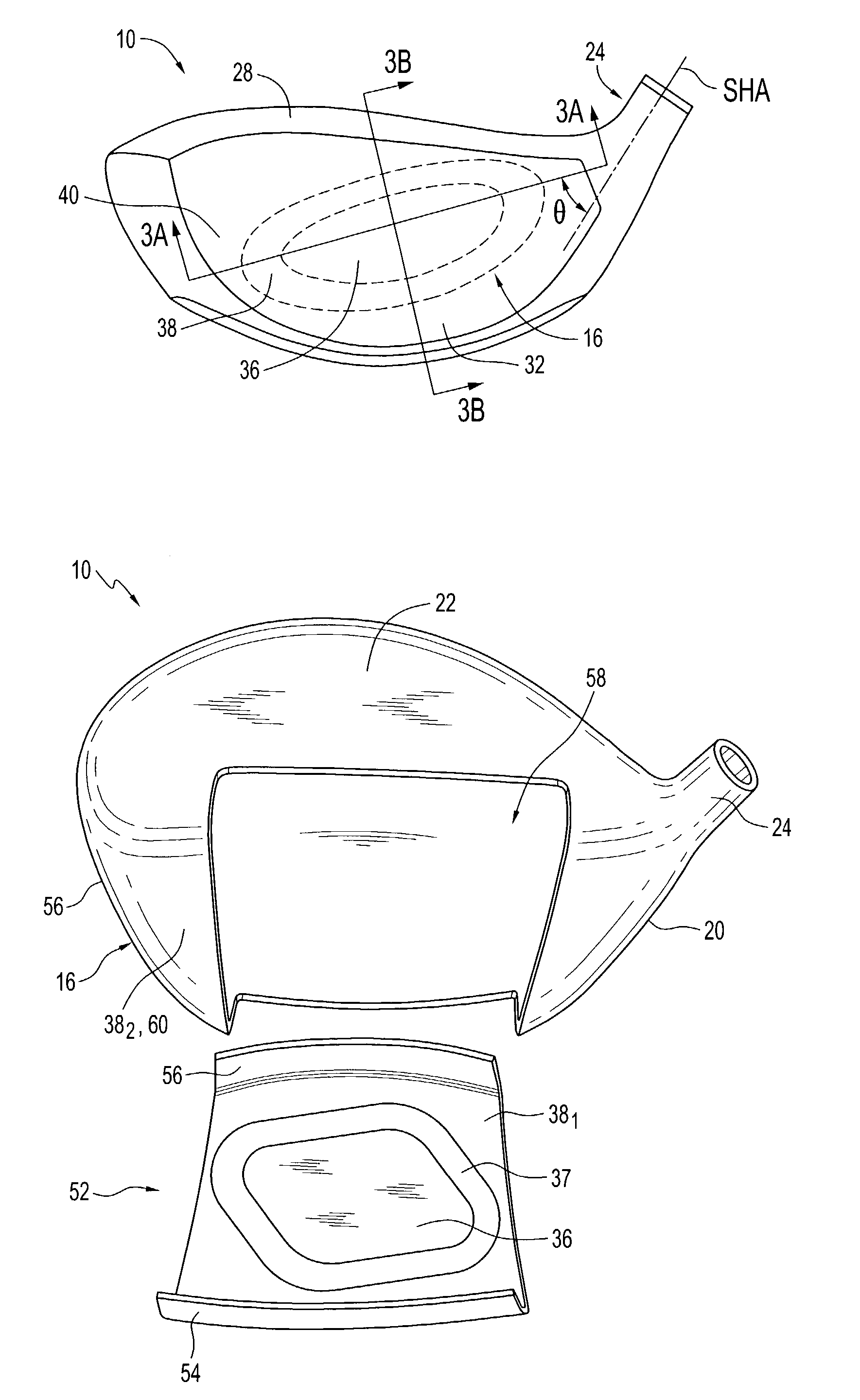
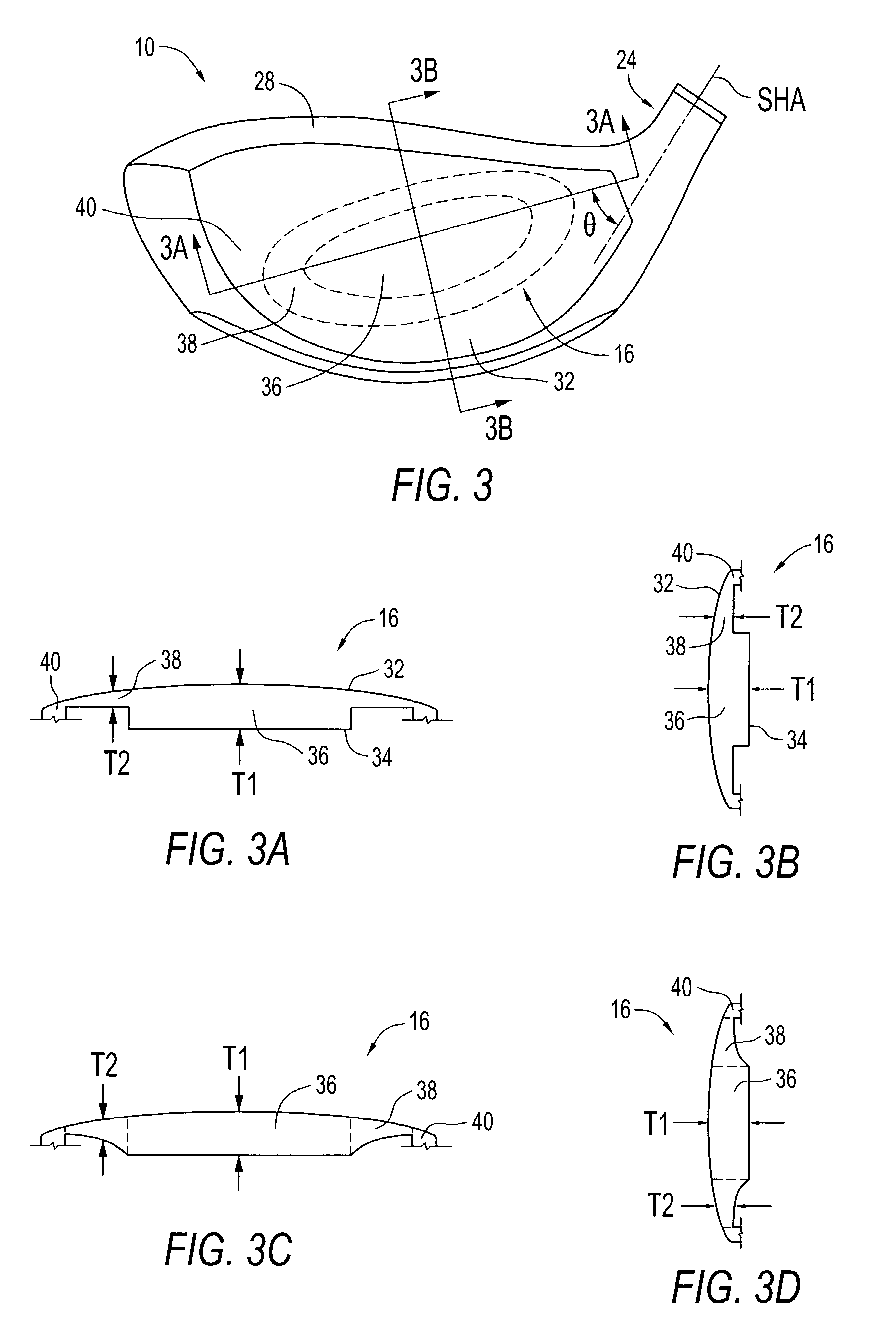
[0056]In this example, hitting face 16 has the following construction. The central zone 36 has a substantially parallelogram shape, as shown in FIG. 10(a), with a major axis measuring about 3 inches and a minor axis about 0.75 inches with a thickness T1, of about 0.120 inch. The central zone 36 has a concentric transition zone 37 with a similar shape as the central zone 36. The intermediate zone 38 surrounds the central and transition zones with a thickness T2 of 0.080 inch and comprises the remainder of the face hitting area. There is no perimeter zone 40 included in this example. The major axis of zone 36 substantially coincides with the major axis of zone 38, and these two major axes form angle theta (θ) of about 50° with the shaft axis. Furthermore, zones 36 and 37 comprise about 18% of the total face surface area. A single homogeneous material, preferably a titanium alloy, with a Young's modulus (E) of approximately 16.5×10⁶ lbs / in2 is used. In this example, the (FS1 / FS2) ratio...


PUM

PropertyMeasurementUnit
angleaaaaaaaaaa
angleaaaaaaaaaa
thicknessaaaaaaaaaa

Abstract

A golf club head having selectively oriented zones of relatively high flexural stiffness is disclosed. The hitting face is configured and dimensioned so that it includes an inner zone and a concentric intermediate zone. The inner zone has relatively high flexural stiffness and the intermediate zone has relatively lower flexural stiffness. The inner zone may have an elliptical shape or a substantially parallelogram shape. Preferably, the inner zone has a shape that comprises a major axis and a minor axis and the major axis aligns substantially in the direction of high heel to low toe. This arrangement of inner and intermediate zones creates a gradient of flexural stiffness in the direction of high toe to low heel and produces a desirable manipulation COR in that direction. This area of high coefficient of restitution advantageously coincides with the ball impact pattern that golfers typically make on the hitting face. The hitting face also comprises a measurement zone wherein the lowest COR is at least 93% of the highest COR.

Description

CROSS-REFERENCE TO RELATED APPLICATION[0001]The present application is a continuation-in-part of U.S. patent application Ser. No. 09 / 551,771 filed on Apr. 18, 2000 and now U.S. Pat. No. 6,605,007. The disclosure of the parent patent application is incorporated herein in its entirety.FIELD OF THE INVENTION[0002]The present invention relates to an improved golf club head. More particularly, the present invention relates to a golf club head with an improved striking face having a zone of high coefficient of restitution aligned in a predetermined orientation.BACKGROUND[0003]The complexities of golf club design are well known. The specifications for each component of the club (i.e., the club head, shaft, hosel, grip, and subcomponents thereof) directly impact the performance of the club. Thus, by varying the design specifications, a golf club can be tailored to have specific performance characteristics.[0004]The design of club heads has long been studied. Among the more prominent conside...

Claims


Application Information

Patent Timeline
Patent Type & Authority Patents(United States)
IPC IPC(8): A63B53/04A63B53/00A63B53/08A63B59/00G01N29/04
CPCA63B53/0466A63B59/0074G01N29/045A63B53/00A63B53/08A63B2053/0416A63B2053/0408A63B2053/0491G01N2291/014G01N2291/02854A63B2053/0458A63B60/42A63B53/0458A63B53/0408A63B53/0416A63B60/00
Inventor RICE, SCOTT ANARDACCI, NICHOLAS M
Owner ACUSHNET CO
Why Eureka
Try Eureka