Method and apparatus for providing high common-mode rejection ratio in a single-ended CMOS operational transconductance amplifier

Active Publication Date: 2006-04-18
XILINX INC
View PDF3 Cites 12 Cited by
  • Summary
  • Abstract
  • Description
  • Claims
  • Application Information

AI Technical Summary

Benefits of technology

[0007]Various embodiments of the present invention provide high common-mode reje

Problems solved by technology

Moreover, for very high frequencies the design of digital circuits becomes more of an analog nature, since the transistor no longer can be considered as a switch.
However, some circ

Method used


Image

  • Method and apparatus for providing high common-mode rejection ratio in a single-ended CMOS operational transconductance amplifier
  • Method and apparatus for providing high common-mode rejection ratio in a single-ended CMOS operational transconductance amplifier
  • Method and apparatus for providing high common-mode rejection ratio in a single-ended CMOS operational transconductance amplifier

Examples


Embodiment Construction

[0022]In the following description of the embodiments, reference is made to the accompanying drawings that form a part hereof, and in which is shown by way of illustration the specific embodiments in which the invention may be practiced. It is to be understood that other embodiments may be utilized because structural changes may be made without departing from the scope of the present invention.

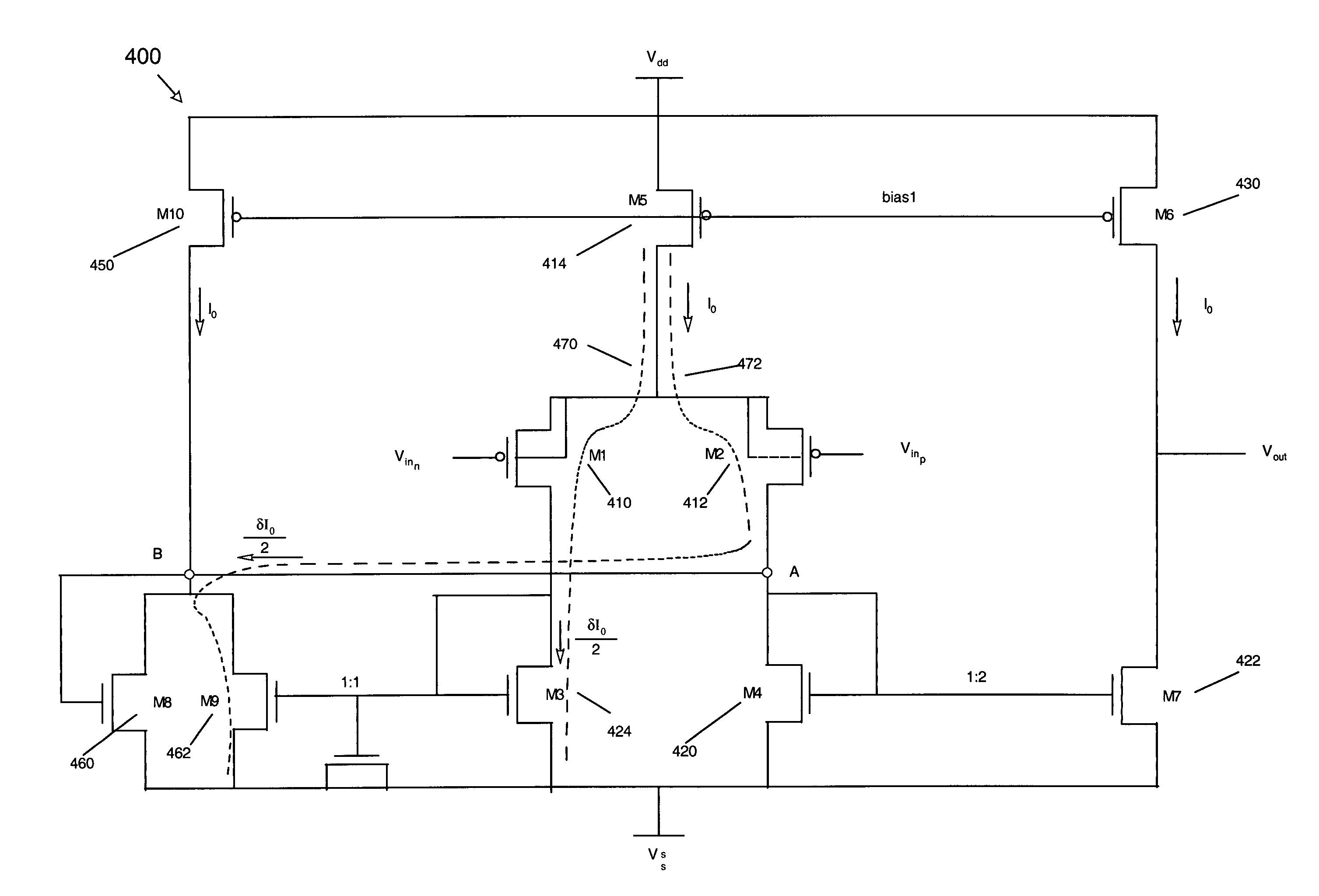
[0023]The present invention provides a method and apparatus for providing high common-mode rejection ratio in a single-ended CMOS operational transconductance amplifier (OTA). Common-mode feedback is used to boost the OTA CMRR, while allowing integration of conventional OTA improvements. The OTA input / output common mode range, die area, power and slewing speed are not affected, but the settling speed is reduced.

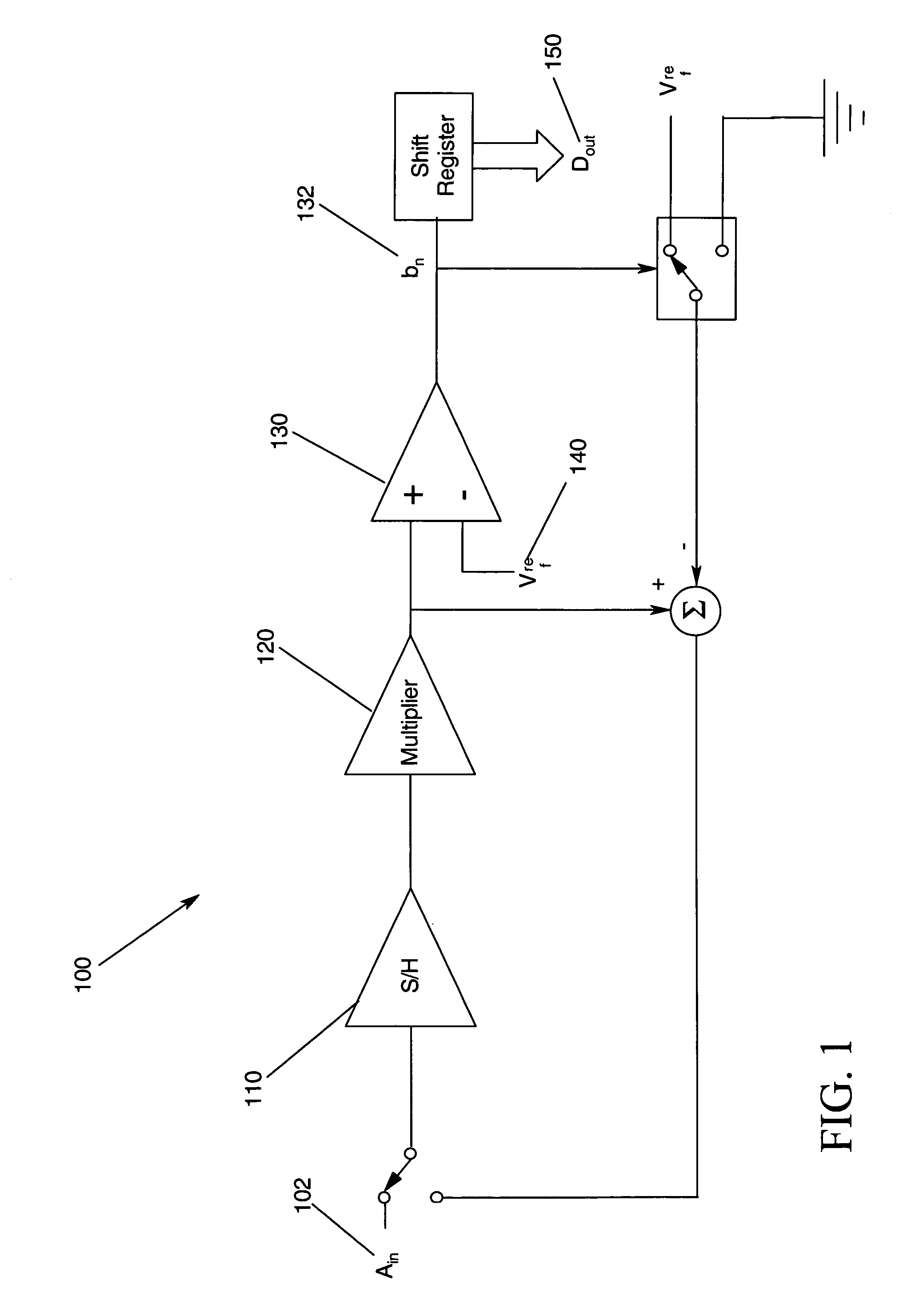
[0024]FIG. 1 illustrates a simplified block diagram 100 of one embodiment of an algorithmic analog-to-digital converter. Those skilled in the art will recognize that there are several t...


PUM


Abstract

A method and apparatus for providing high common-mode rejection ratio (CMRR) in a single-ended CMOS operational transconductance amplifier is disclosed. A common-mode feedback boosts the OTA CMRR, while allowing integration of conventional OTA improvements.

Description

FIELD OF THE INVENTION[0001]This invention relates in general to Complementary Metal-Oxide Semiconductor (CMOS) amplifiers, and more particularly to a method and apparatus for providing high common-mode rejection ratio in a single-ended CMOS operational transconductance amplifier.BACKGROUND[0002]Over the last few decades, analog integrated circuits have more and more been replaced by digital circuits because digital circuits tend to be less noisy, require a lesser area per complexity. However, the outside world is of analog nature and to be able to interact with computers, etc., some amount of analog circuits, e.g., filters and amplifiers, and mixed analog / digital circuits, e.g., digital-to-analog and analog-to-digital converters, are needed. Moreover, for very high frequencies the design of digital circuits becomes more of an analog nature, since the transistor no longer can be considered as a switch.[0003]The circuit industry has witnessed increasing levels of integration for such...

Claims


Application Information

Patent Timeline
IPC IPC(8): H03F3/45
CPCH03F3/45192H03F3/4569H03F2203/45028
Inventor PRIBYTKO, MAXIMQUINN, PATRICK J.
Owner XILINX INC
Why Eureka
Try Eureka