Digital camera and exposure control method of digital camera

a digital camera and exposure control technology, applied in the field of cameras, can solve the problems of blurred shot image, missed good moment to take a picture, and inability to ensure that an appropriate program line is selected

Inactive Publication Date: 2006-04-18
SEAGATE TECH LLC +1
View PDF13 Cites 63 Cited by
  • Summary
  • Abstract
  • Description
  • Claims
  • Application Information

AI Technical Summary

Benefits of technology

[0008]To achieve the above-mentioned object, a digital camera according to the present invention comprises: an image sensing unit for sensing a subject image; a detector for detecting a degree of correlation between image data of a plurality of frames from said image sensing unit before shooting; an exposure controller for, in a case where the degree of correlation is low as a result of the detection by said detector, controlling an exposure time of said image sensing unit so as to be shorter than an exposure time in a case where the degree of correlation is high; and a recorder for recording image data from said image sensing unit controlled by said exposure controller.
[0009]Further, as another invention for achieving the above-mentioned object, a digital camera comprises: an image sensing unit for sensing a subject image; a detector for detecting a degree of correlation between image data of a plurality of frames from said image sensing unit before shooting; a memory for storing a first program and a second program to control an exposure time of said image sensing unit respectively, wherein the exposure

Problems solved by technology

However, in a case where the exposure conditions are set based on the subject brightness or the like, the shot image is blurred when the subject moves by some amounts.
Moreover, in a camera provided with a plurality of program lines, there is a possibility that a good moment to take a picture is

Method used


Image

  • Digital camera and exposure control method of digital camera
  • Digital camera and exposure control method of digital camera
  • Digital camera and exposure control method of digital camera

Examples


Embodiment Construction

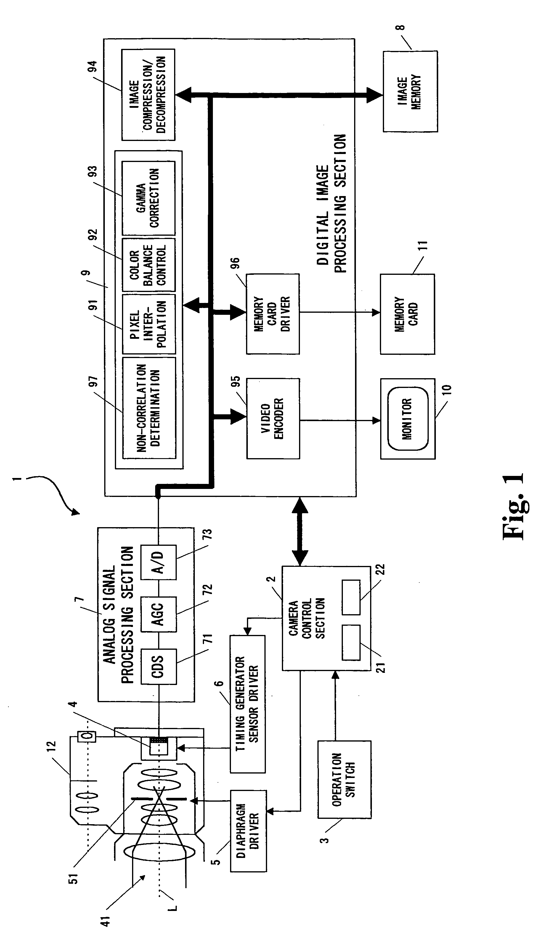
[0023]FIG. 1 is a block diagram showing an embodiment of a control configuration of a digital camera according to the present invention. In FIG. 1, the digital camera 1 comprises: a camera control section (CPU) 2 for controlling shooting in accordance with a shooting control program stored in a data storage section 21; an operation switch 3; an imaging section 4 for forming a subject light image; a diaphragm driver 5 for controlling the aperture of a diaphragm 51 interposed on the optical axis L; a timing generator and sensor driver 6 (hereinafter, abbreviated as driver 6) for controlling the exposure time and charge transfer; an analog signal processing section 7; an image memory 8 serving as a work memory; a digital image processing section 9; and a monitor 10 such as a liquid crystal display. A memory card 11 is designed so as to be detachably attachable to a camera body 12, and has a capacity sufficient for storing image data corresponding to a plurality of frames.

[0024]The oper...


PUM


Abstract

Two subject images shot by an imaging section before real exposure are captured, and the difference between data is obtained for each corresponding pixels of the subject images by an interframe difference calculation section. The difference is compared with a threshold value by a threshold value comparison section, the pixels of levels not less than the threshold value level are extracted as a non-correlated portion, and the ratio of the area of the non-correlated portion to all the detected pixels is obtained by a non-correlated portion area calculation section. When the ratio of the area of the non-correlated portion is high, it is determined that the subject movement is large, so that a speed priority program line is selected by an exposure calculation block and the exposure time is set to be shorter than the normal exposure time, thereby preventing subject image blur.

Description

[0001]This application is based on the application No. 11-274400 filed in Japan, the content of which is hereby incorporated by reference.BACKGROUND OF THE INVENTION[0002]1. Field of the Invention[0003]The present invention relates to a camera such as a digital camera and a silver halide film camera for shooting a subject, and more particularly, to setting of shooting conditions.[0004]2. Description of the Related Art[0005]A camera has previously been known in which the aperture value Av and the exposure time (shutter speed) Tv which are exposure conditions are set by the user when shooting is performed. Moreover, a camera has previously been known in which in order to reduce the load of setting on the user, the aperture value Av and the exposure time Tv previously obtained by use of a relationship Ev=Av+Tv for each of the exposure amounts Ev corresponding to subject brightnesses obtained by photometric means are provided in the form of a table (a program line), and the aperture val...

Claims


Application Information

Patent Timeline
IPC IPC(8): H04N5/235G03B7/097H04N5/335H04N5/353H04N5/355H04N5/357H04N5/363H04N5/369H04N5/378
CPCH04N5/2352H04N5/2351H04N23/72H04N23/71
Inventor KUBO, HIROAKI
Owner SEAGATE TECH LLC
Why Eureka
Try Eureka