Color image pickup apparatus with light source distinguishing function

a pickup apparatus and light source technology, applied in the field of color image pickup apparatus, can solve the problems of inability to apply the above-described assumptions, the photograph image has a large white imbalance, and the digital camera cannot correctly distinguish between different light sources

Inactive Publication Date: 2006-04-18
FUJIFILM CORP
View PDF3 Cites 20 Cited by
  • Summary
  • Abstract
  • Description
  • Claims
  • Application Information

AI Technical Summary

Benefits of technology

[0016]The color image pickup apparatus can distinguish between an illuminating light source such as fluorescent light having a relatively small radiation energy in the wavelength range of 640 nm or longer and an illuminating light source such as sun light and incandescent light having a relatively large radiation energy in the wavelength range of 640 nm or longer. It is possible to adjust white balance matching each illuminating light source.

Problems solved by technology

Some digital cameras cannot correctly distinguish between different light sources.
If distinguishment is impossible between sun light and fluorescent light, a photographed image has a large white imbalance.
In practice, however, there are many scenes to which the above-described assumptions cannot be applied.
For example, a semi-dark scene full of green leaves under sun light is similar to a scene under a standard white fluorescent lamp, a daylight fluorescent lamp or a neutral white fluorescent lamp so that a light source distinguishing error is likely to occur.
If the white balance is poor, it is difficult to adjust the color of an image after it is taken.
It is not practical if a photographer manually sets a white balance by distinguishing the kind of each light source.

Method used


Image

  • Color image pickup apparatus with light source distinguishing function
  • Color image pickup apparatus with light source distinguishing function
  • Color image pickup apparatus with light source distinguishing function

Examples


first embodiment

[0042]Basing upon the above-described studies, a solid image pickup device according to the invention will be described with reference to FIGS. 2 to 9.

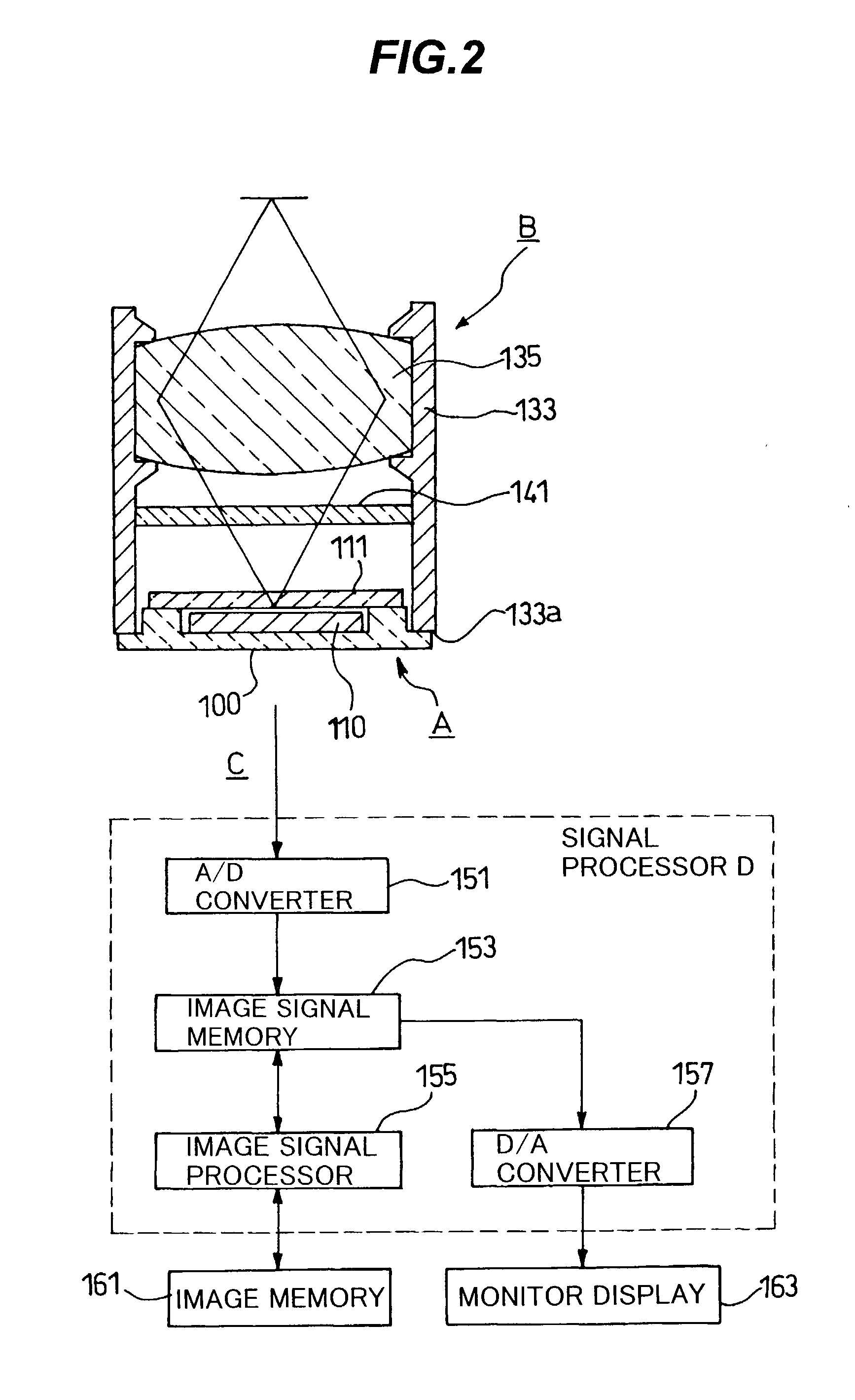
[0043]FIG. 2 is a schematic diagram showing the outline structure of a color image pickup apparatus (digital still camera) of the embodiment. The color image pickup apparatus C has an image pickup unit B, a signal processor D, an image memory (storage device) 161, and a monitor display 163. An infrared cut filter 141 is disposed between a taking lens 135 and a sealing plate 111. The sealing plate 111 is made of, for example, a crystal plate cut to have a special orientation, and functions also as a low pass filter.

[0044]FIG. 5 is a diagram showing the wavelength dependency of transmission factors of an IR (infrared) cut filter and an LR (long red) pass filter of this embodiment. The IR cut filter 141 lowers the transmission factor at the wavelength of 655 nm or longer (at which the transmission factor is 50%). The transmission factor ...

second embodiment

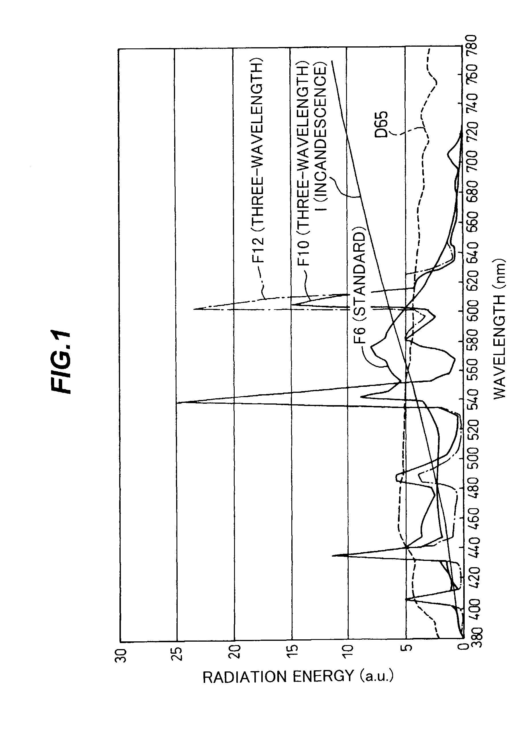
[0100]Next, a color image pickup apparatus according to the invention will be described with reference to FIG. 1 and FIGS. 10 to 12. FIG. 10 is a spectrum diagram showing relative spectral sensitivities of F6 detecting photoelectric conversion elements of a solid state image pickup apparatus using yellow filters. FIG. 11 is a spectrum diagram showing relative spectral sensitivities of F6 detecting photoelectric conversion elements and RGB photoelectric conversion elements. FIG. 12 is a graph showing Y / (R+G) values (ratios of an output of a photoelectric conversion element with an Y filter to a sum of outputs of photoelectric conversion elements with R and G filters) under various illuminating light sources.

[0101]As shown in FIG. 1, the standard white fluorescent lamp (F6) among the fluorescent lamps has a small radiation energy in the red wavelength range, and color distortion is likely occur even if AWB is correctly performed by a camera. A human skin (flesh) color becomes yellowis...

fourth embodiment

[0120]Next, a color image pickup apparatus will be described with reference to FIGS. 1, 14 and 15. FIG. 14 is a spectrum diagram showing spectral sensitivities (relative sensitivities) of an illuminating light source detecting photoelectric conversion element with an YLR filter of a solid stage image pickup device. In this specification, a filter having a high transmission factor in the yellow and long red wavelength ranges is called YLR filter. FIG. 15 a diagram showing YLR / (R+G) values of a color image pickup device under various illuminating light sources, YLR / (R+G) being a ratio of an output of a photoelectric conversion element with an YLR filter to a sum of outputs of photoelectric conversion elements with R and G filters.

[0121]In the color image pickup apparatus of the first embodiment, by using an LR filter and infrared cut filter, a filter having a transmission factor substantially only in the frequency range from 640 nm to 680 nm is formed. In this case, as described earl...


PUM


Abstract

An image pickup system includes photodiodes with color filters. A first color filter group includes visual light color filters, and a second color filter group includes a long red color filter at 640 nm or longer or a color filter at 580 nm and one of the visual light color filters. An infrared cut filter covers all the filters. A control circuit includes a fluorescent lamp distinguishing circuit for distinguishing a fluorescent lamp from other illuminating light sources by a ratio of an output signal from the photodiode with the long red filter to an output signal from the photodiodes with the visual light color filters; and a white balance control circuit for adjusting a white balance so as to match the illuminating light source distinguished by the fluorescent lamp distinguishing circuit.

Description

CROSS REFERENCE TO RELATED APPLICATION[0001]This application is based on Japanese Patent Application No. 2001-285403, filed on Sep. 19, 2001 and Japanese Patent Application No. 2002-090427, filed on Mar. 28, 2002, the entire contents of which are incorporated herein by reference.BACKGROUND OF THE INVENTION[0002]A) Field of the Invention[0003]The present invention relates to a color image pickup apparatus and more particularly to a color image pickup apparatus capable of obtaining a good white balance independently from the kinds of illuminating light sources.[0004]B) Description of the Related Art[0005]Technical advance of digital still cameras and digital video cameras (hereinafter collectively called “digital camera”) is remarkable. Most of digital cameras are equipped with an auto white balance (AWB) mechanism which distinguishes between different light sources and automatically adjusts a white balance.[0006]Some digital cameras cannot correctly distinguish between different ligh...

Claims


Application Information

Patent Timeline
Patent Type & Authority Patents(United States)
IPC IPC(8): H04N9/83H04N9/73G02B5/20G02B5/22G02B5/26H04N9/04H04N9/07
CPCH04N9/045H04N5/332H01L27/14621H01L27/14868H01L27/14683H04N23/11H04N25/134
Inventor AOTSUKA, YASUO
Owner FUJIFILM CORP
Why Eureka
Try Eureka