Liquid crystal display device with roughened surfaces to reduce moiré fringe effects

a liquid crystal display and moiré fringe technology, applied in the field of liquid crystal display devices, can solve the problems of affecting display quality, affecting display quality, and no lens sheet with a high light condensing effect, and achieve the effect of improving display quality

Inactive Publication Date: 2006-04-18
GOLD CHARM LTD
View PDF29 Cites 31 Cited by
  • Summary
  • Abstract
  • Description
  • Claims
  • Application Information

AI Technical Summary

Benefits of technology

[0027]The present invention has been made in consideration of the above situation in the prior art, and has as its object to provide a liquid crystal display device in whic

Problems solved by technology

Accordingly, liquid crystal display devices are also becoming low-profile and lightweight.
In this prior art, a group of substantially parallel ring-like curves (fringes) form to produce display nonuniformity, impairing the display quality.
Other than a prism type lens sheet, however, no lens sheet is available which has a high light condensing effect and can be available at a low cost almost equal to that of the prism type lens sheet.
If an optical member such as a diffusing sheet is further used to suppress the moiré fringe, the thickness of the liquid crystal display device increases, leading to an additional increase in cost for this optical member.
If the surface roughnesses are increased so that the grating fringes become thin with only the antiglare process for the polarizing plates, light from the backlight is scattered by the roughened surfaces to decrease the luminance, which is another problem.
This is because the use of a prism type lens sheet is use

Method used


Image

  • Liquid crystal display device with roughened surfaces to reduce moiré fringe effects
  • Liquid crystal display device with roughened surfaces to reduce moiré fringe effects
  • Liquid crystal display device with roughened surfaces to reduce moiré fringe effects

Examples


Embodiment Construction

[0048]Some preferred embodiments of the present invention will be described below in detail with reference to the accompanying drawings.

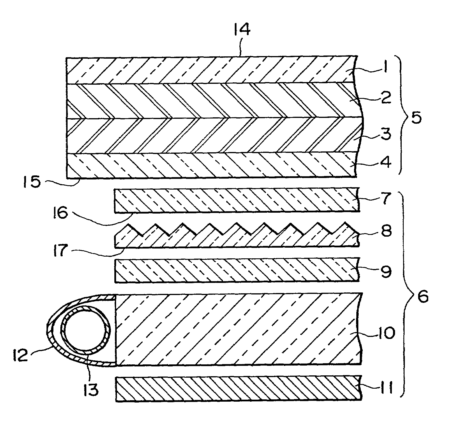
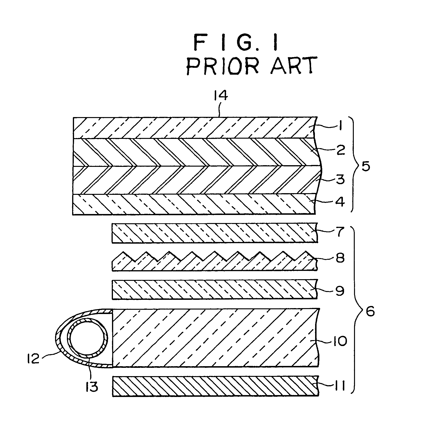
[0049]FIG. 4 is a sectional view showing the arrangement of a liquid crystal display device according to an embodiment of the present invention. This liquid crystal display device is mainly comprised of a liquid crystal display panel 5, backlight unit 6, driver IC (not shown) for driving the liquid crystal display panel 5, and signal control circuit (not shown) for the driver IC. The liquid crystal display panel 5 is comprised of upper and lower electrode substrates 2 and 3 arranged adjacent to each other to form an electrode substrate unit, and upper and lower polarizing plates 1 and 4 respectively adhered to the outer surfaces of the upper and lower electrode substrates 2 and 3. The backlight unit 6 is comprised of a fluorescent tube 13 serving as a light source, reflector 12, light guide plate 10, reflecting sheet 11, diffusing sheet 9, upper len...


PUM


Abstract

A liquid crystal display device includes a liquid crystal display panel obtained by adhering upper and lower polarizing plates to upper and lower surfaces, respectively, of an electrode substrate. The upper polarizing plate has a first roughened surface on its outer surface. The first roughened surface is formed for the purpose of antiglare. The lower polarizing plate has a second roughened surface on its outer surface. The second roughened surface is formed to have a surface roughness equivalent to or less than that of the first roughened surface. As a result, a moiré fringe is decreased.

Description

BACKGROUND OF THE INVENTION[0001]1. Field of the Invention[0002]The present invention relates to a liquid crystal display device and, more particularly, to a liquid crystal display device in which occurrence of a moiré fringe is suppressed and display nonuniformity produced by a moiré fringe is accordingly decreased so that display quality is improved.[0003]2. Description of the Prior Art[0004]In recent years, notebook type personal computers are becoming remarkably low-profile and lightweight so that they can be carried easily. Accordingly, liquid crystal display devices are also becoming low-profile and lightweight. Making low-profile a transmission liquid crystal display device having a backlight amounts to making the backlight low-profile. Components most influenced by rendering the backlight low-profile include a light guide plate. Making the light guide plate low-profile narrows its light-incident end face and decreases the incident light amount, leading to a decrease in lumin...

Claims


Application Information

Patent Timeline
IPC IPC(8): G02F1/1335G09F9/00G02B5/02G02F1/1333G02F1/13357
CPCG02F1/133528G02F1/133615G02F1/133707G02F1/1335
Inventor FUJIMOTO, KAZUSHI
Owner GOLD CHARM LTD
Why Eureka
Try Eureka