

Apparatus and method for detecting an abnormality in a recorded signal
a recording apparatus and abnormality technology, applied in the field of abnormality detection in recorded signals, can solve the problems of undesired abnormal signal recording or reproducing, high possibility of foreign substances being transferred from the magnetic tape to the head, abnormal recording/reproduction, etc., to achieve efficient and elegant addition of important and useful functions to the recording apparatus, and efficient design. , the effect of less efficient design
- Summary
- Abstract
- Description
- Claims
- Application Information
AI Technical Summary
Benefits of technology
Problems solved by technology
Method used
Image

Examples
first embodiment
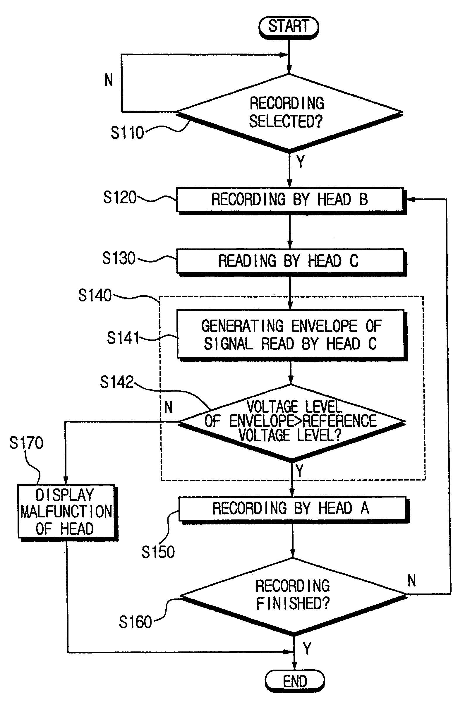
[0081]FIG. 13 is a flow chart for explaining a method for detecting abnormality of recorded signal according to second preferred embodiment of the present invention. In this embodiment, the steps of selecting recording operation (S110), recording by the head B (S120), reading by the head C (S130), recording by the head A (S150), determining if recording is finished (S160), and displaying malfunction (S170) are similar to the corresponding steps described above in the description of the first embodiment, with reference to steps 10, 20, 30, 50, 60, and 70 of FIG. 12, respectively.
second embodiment
[0082]The method of detecting an abnormality in a recorded signal as illustrated in FIG. 13 is different from the method of detecting an abnormality in a recorded signal as illustrated in FIG. 12. The step S40 in FIG. 12 is not the same as the step S140 in FIG. 13. Accordingly, the step S140 of detecting abnormality of recorded signal, which is the unique feature of the second embodiment, will now be described below in greater detail.
[0083]The step S140 of FIG. 13 includes the substeps S141 and S142. At step S141, an envelope is generated of the signal reproduced by head C. At step S142, the voltage level of the envelope is compared with a reference voltage level. If the voltage level of the envelope is greater than or equal to the reference voltage level, then the microcomputer 90 determines that no abnormalities exist and then head A records data at step S150. Otherwise, step S170 is performed to alert a user to an abnormality in the recording operation.
[0084]Immediately after the...
PUM
| Property | Measurement | Unit |
|---|---|---|
| angle | aaaaa | aaaaa |
| angle | aaaaa | aaaaa |
| time | aaaaa | aaaaa |
Abstract
Description
Claims
Application Information